


Measurements of electrical quantities of PC power supplies
The time has come to introduce the testing methodology for computer PSUs. We will divide this into two articles, where the first will cover procedures for obtaining key electrical quantities (i.e. surrounding efficiency, voltage regulation, voltage ripple, etc.). A separate sequel will then focus on the analysis of acoustic profiles. But now on to the purpose for which we travelled to the external testlab.
We have been collecting ATX 3.0 PSU samples since the beginning of this year. From time to time we have been releasing “previews” with design details for each unit. The main thing, to be able to evaluate which PSU performs how and in what, comes only now. It all started with finding a place, or rather a testlab, where the main electrical quantities could be measured. We approached Enermax about this because we know they have a programmable current load (i.e., a device that can be used to load PSUs as desired) and all the things we need for these purposes. In the past, the Enermax testlab also hosted former colleagues from the long-defunct magazine ExtraHardware.cz.
If you thought that Enermax wanted something in return for this service, which would reek of manipulation in their favour, they really didn’t. The only condition was that they would be the only company in the tests to have two power supplies. They have one model in the core twelve like everyone else and at the end a second model. On top of that, we also bartered off our visit to the Enermax testlab with a banner, which you may have noticed in the space above the comments section. That’s just for completeness, to make it clear under what conditions things were taking place.
And why did we go anywhere at all? We don’t own the equipment to test PSUs, and when it comes to a full set of devices, it’s not cheap. Investing in them doesn’t make sense to us in terms of our primary focus and what we want to do on a regular basis in the future. That’s why we decided to approach someone who is more intensively involved in the issue of PSUs and also has the right background to test them. And now for “what” we came for – Chroma devices.
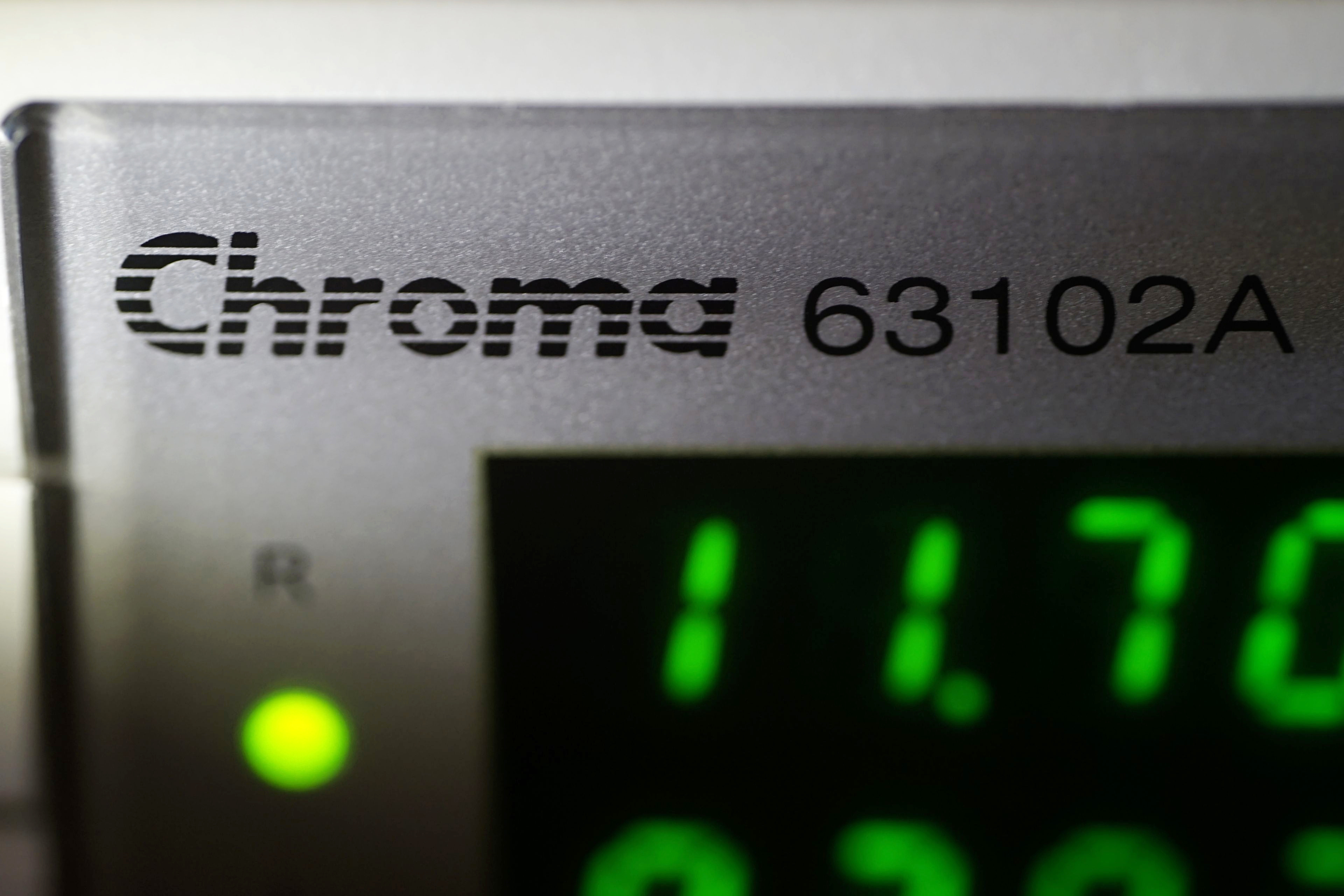

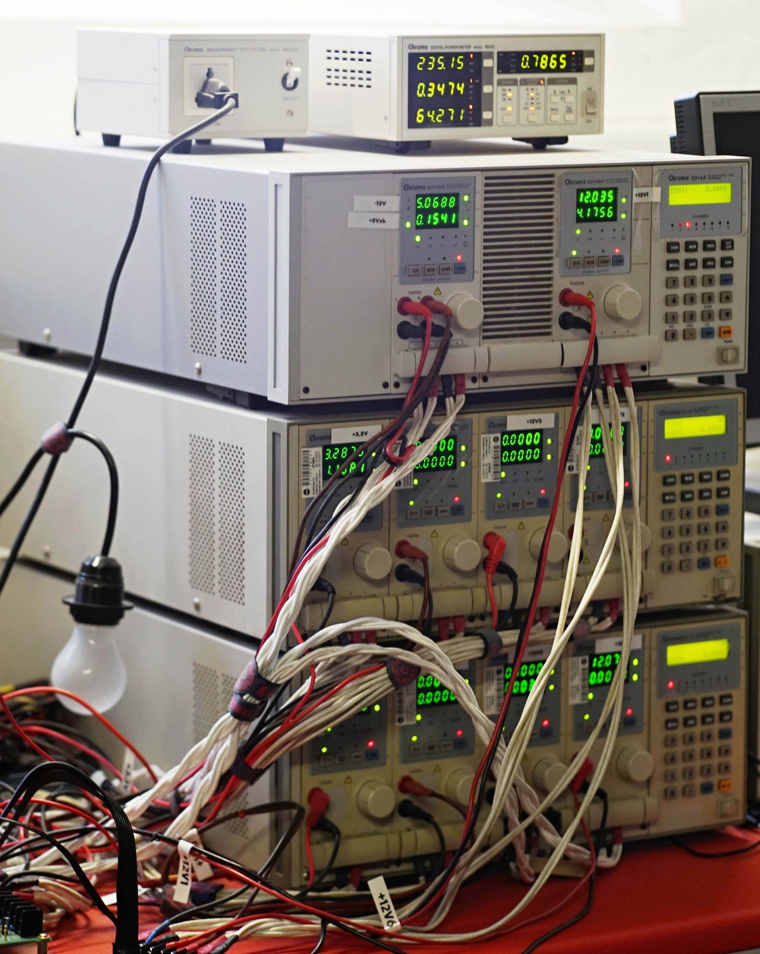
For PSU tests, something that can accurately (and comparably) load them is important in the first place. For this, we had three racks with ten load modules, some of which were up to 300 W, others up to 600 W. However, in the right combination, it is possible to have a much higher load than that required for a PSU with a labelled power of 850 W (i.e., which is what the vast majority of our test models have). With the exception of the weak rails (5 VSB and -12 V, Chroma 63102A), each rail is loaded by a different module, and we use up to two load modules (Chroma 63106A) to load the strong rail with +12 V.
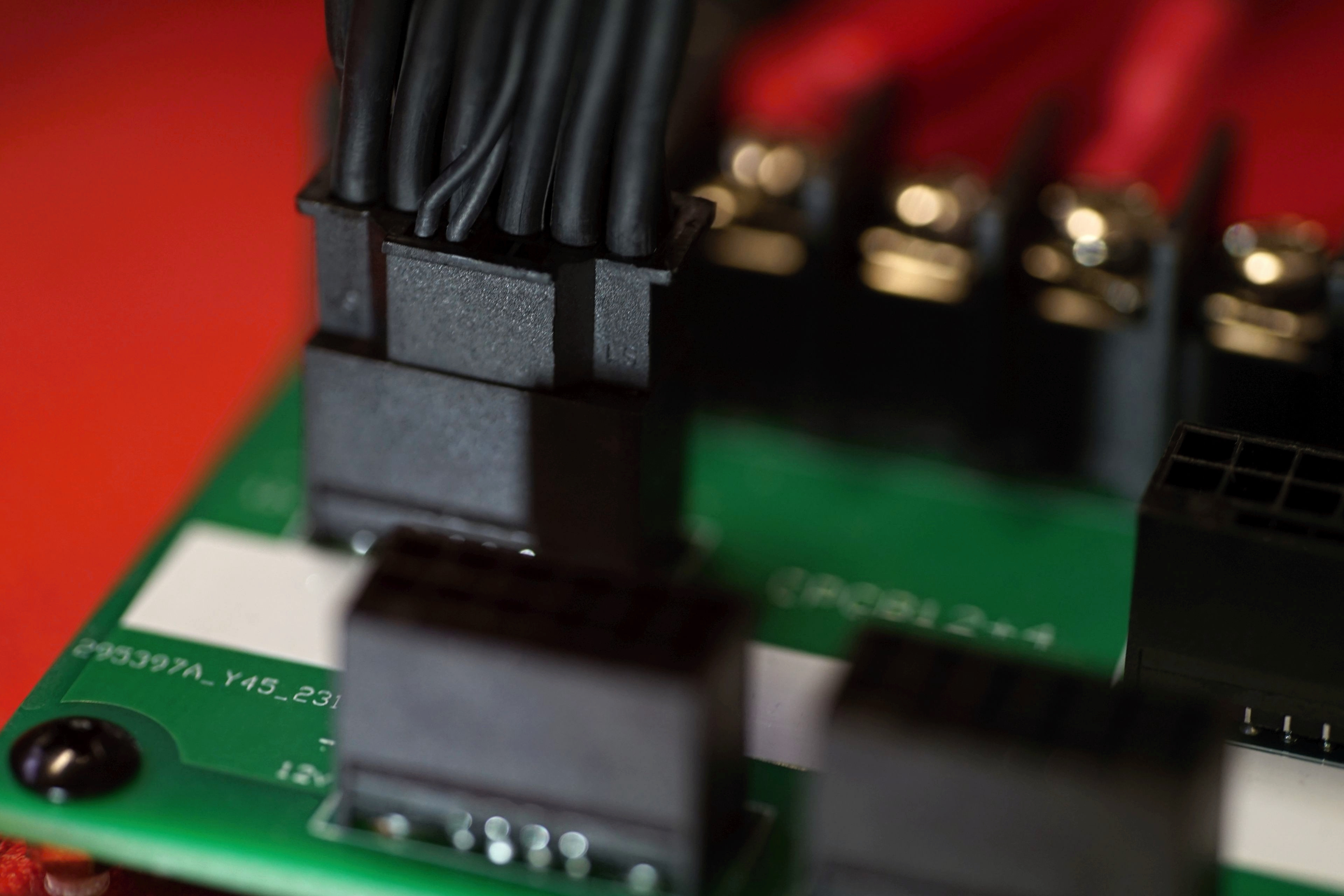
The PSUs are connected to the current load via PCBs with connectors that you know from motherboards or PSUs. This is done in such a way that the current always flows through a large enough cross-section to avoid melting the cable insulation. For a more even load, we use one more, secondary board in addition to the “main” board with ATX connector and 6+2-pin (PCIe) and 8-pin connectors (for CPU power).
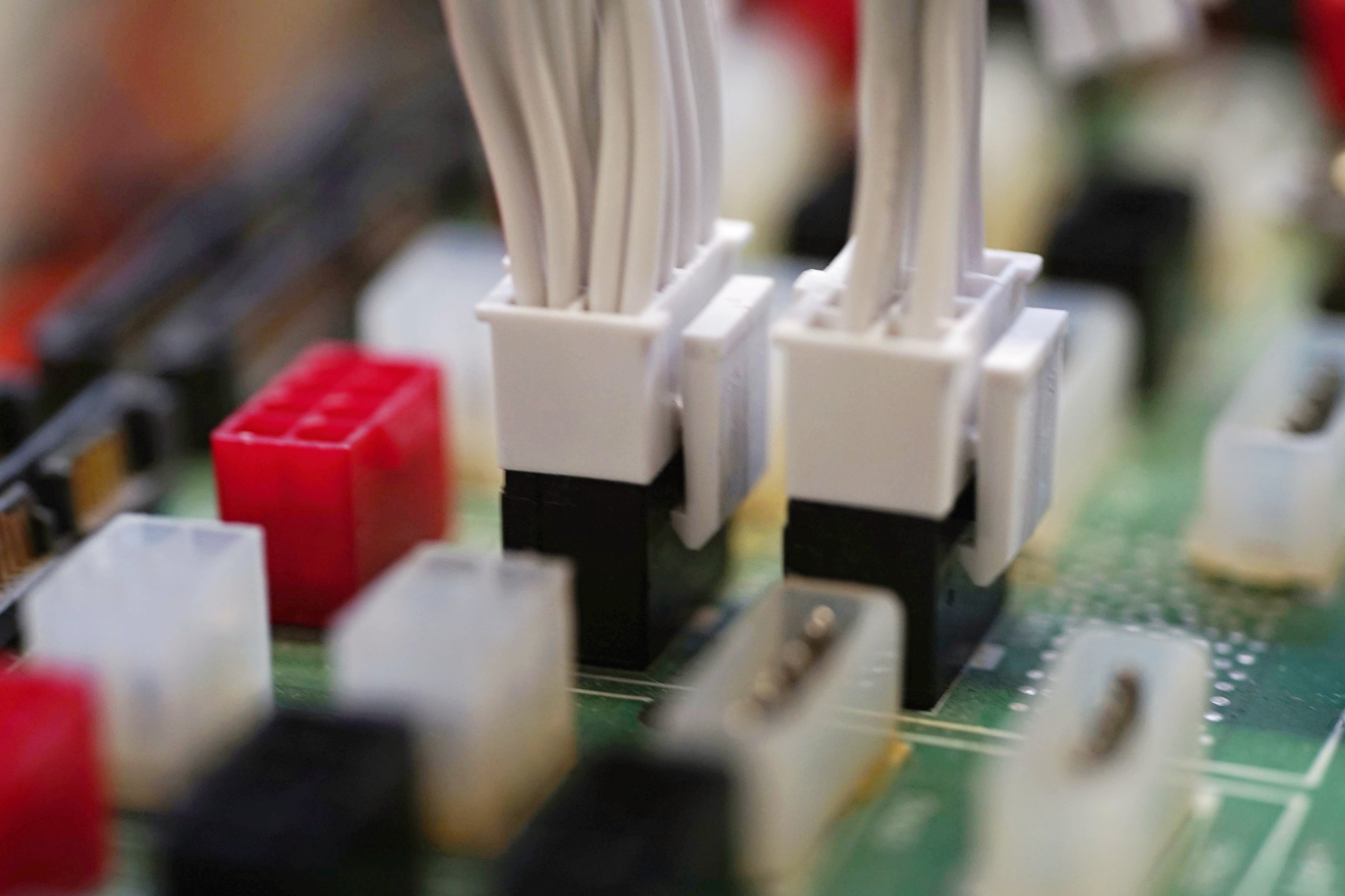
At the last minute we managed to get our hands on a board with 12VHPWR connectors. Thanks to this, you may have already read our comparative test with 12VHPWR cable temperatures. This is how we started the test of each PSU and we used these measurements, in addition to analyzing the temperature, to record the voltage at the clamps (PCB) before the end of the test (after 540 seconds) with a properly calibrated Keysight U1231A multimeter. This nicely illustrates the voltage drop due to cable resistance (12VHPWR) at high load (53 A).
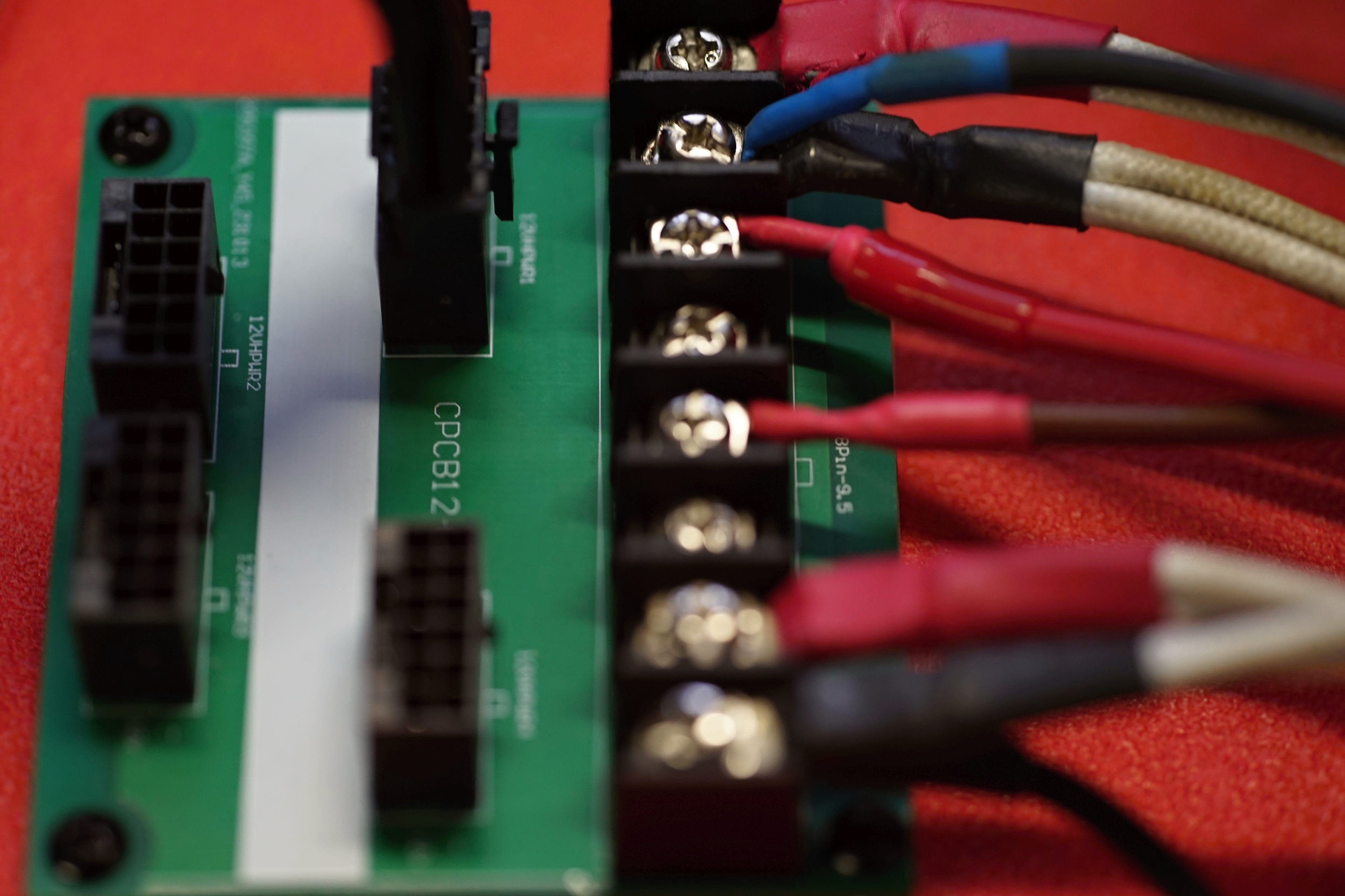
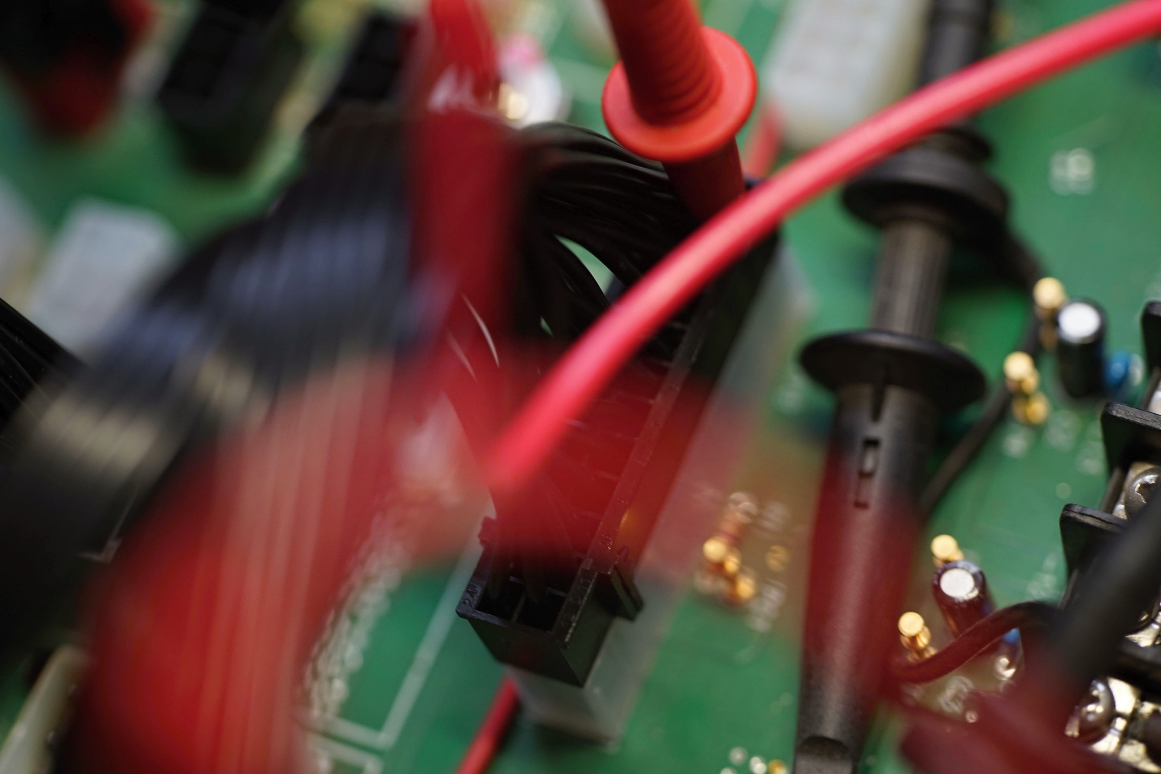
To obtain voltage regulation data, the probes (already at different load levels) were connected directly to the corresponding contacts at the end of the 24-pin ATX connector.
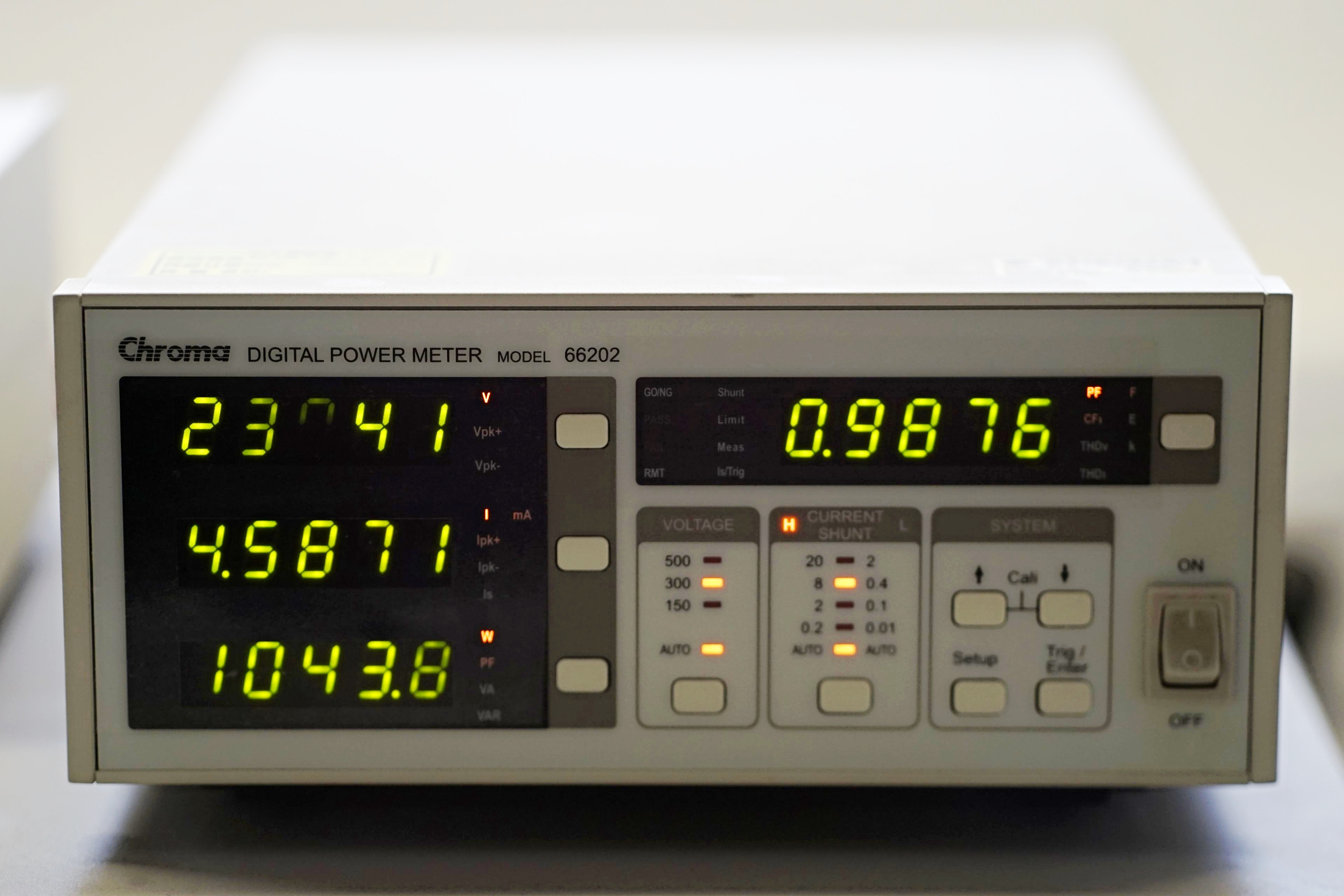
A very important element of the measurement set-up is the power meter Chroma 66202. It allows an overview of the power draw, which is necessary for the calculation of efficiency (in proportion to the power). In addition, power factor (PFC) values can also be read from this device. The closer it is to 1 (where 1 is also the maximum), the lower the reactive power of the PSU. This may not be of interest to small consumers, but it is also an indicator that speaks to the qualitative characteristics of the PSU design.
Finally, a Tektronix TDS 3014C oscilloscope is connected to the 12; 5 and 3.3 V rails to monitor voltage ripple at different load levels.

To conclude, it is worth noting that this is our first experience with PSU tests and also due to the inappropriate amount of time (we only had 14 hours for 12 PSUs, including instruction on how to use the Chroma devices), it was not possible to have everything in the quality we would have liked. Also shorter than would have been appropriate were the time intervals (lasting only 120 seconds) after which readings were taken for the set load modes. Due to human error, we (and here to be safe I will drop the author’s plural so as not to appear as the fault of anyone other than myself) miscalculated the current values and instead of 5; 20; 50; 70 and 100 percent loads we have results from 5.7; 22.8; 57; 79.8 and 113 percent loads (the highest load, by the way, shows that each PSU can handle a sustained overload of 13 percent, albeit at the expense of lower efficiency).
I am very sorry for the above mentioned inaccuracy, personally I consider it the biggest oversight in my practice as a hardware tester so far. We found it unfortunately too late, when retesting was no longer possible. Still, you get a relatively full comparison of the tested PSUs, although against the official parameters or results from other tests, ours cannot stand up. But this would not be the case even with appropriately set loads, because the Chroma system does not have a valid calibration, or adjustment, and so some deviation must be expected against benchmarks, although it will probably be very small, negligible.
The tests are carried out at 230 V and the ambient air temperature ranged from 18.8 to 19.2 °C.
Next time, in the next article, we will meet with noise measurements, which will also include frequency analysis of the sound of the interaction between the fan and the grille (and cooling shield) of the PSUs. These measurements are already underway in our testlab.
English translation and edit by Jozef Dudáš