


Analysis of the SilverStone aerodynamic grille
Every SilverStone Air Penetrator series fan includes an aerodynamic grille on the exhaust. This is firmly attached to the frame, but can be forcibly removed. The AP123 fan has gone through such a process and we will demonstrate the benefits of this grille. Whether it is good or bad cannot be noted briefly, but the way SilverStone communicates it to the public is again a bit unfortunate and misleading.
SilverStone likes grilles and the topics around them.
You may have recently read a complete analysis of the AP123 fan, which clearly shows SilverStone has no problem pulling your leg just to artificially create a competitive advantage. Although therefore not based on truth, as far as the mystification is concerned, it is not true that the hexagonal grille in front of the rotor (on the intake side) does not increase the noise level of the fan. Now we’ll talk about the grille again, but it’ll be a slightly different story. In principle, this is no longer a fabrication and the grille on the fan exhaust does indeed work as SilverStone describes, but is it put into practice well?
The aerodynamic grille on the AP SilverStone fans consists of curved fins with an “I” profile of 3 mm height and 1.6 mm width. They are rectangular in cross-section, i.e. with right-angled corners. In its materials, SilverStone notes in text, illustrations, and on video how this grid changes the flow trajectory and narrows the airflow span.
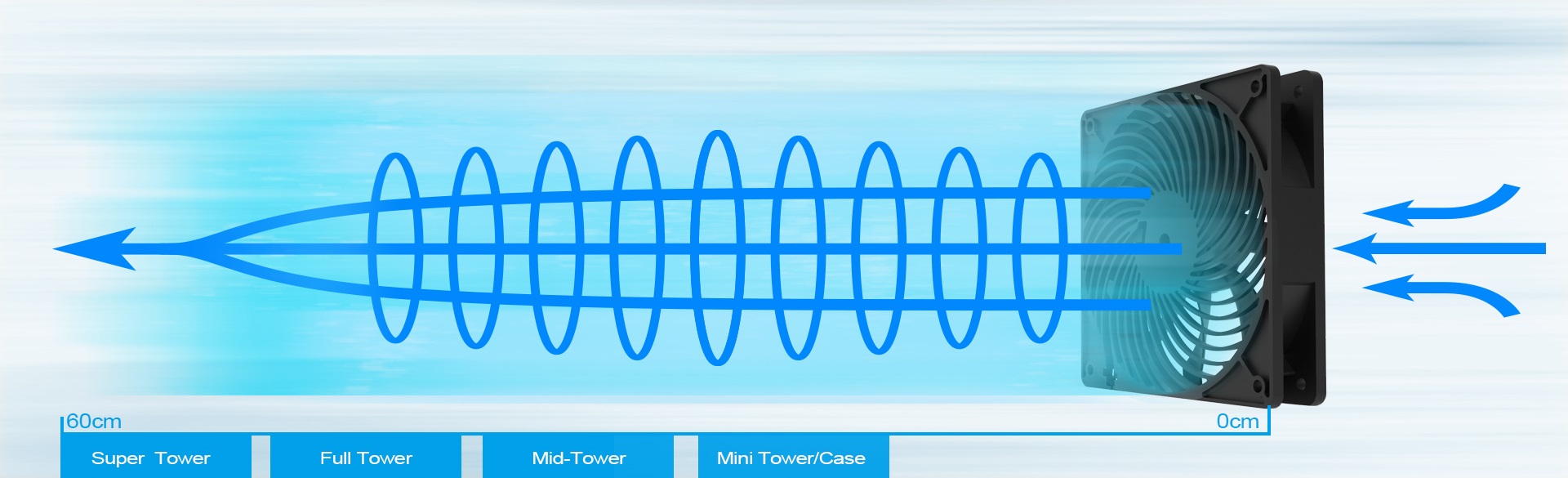
In other words, the airflow is more direct and does not go sideways as with fans that do not have such a grille.
This allows the fan to exert a higher overall pressure in an open space over a greater distance, for example two meters, as SilverStone emphasizes with the Air Penetrator 140i, for example.
This is true, and indeed the Air Penetrators will have more range (in terms of total pressure) than other fans. That’s because the grille creates a similar effect to when you squeeze a hose with water flowing through it. The effect of the change in pressure by constricting the throat is that you get more range, but you don’t pump more volume.
For some applications, this behavior can be useful when we relate it again to that fan situation. In setups with passive coolers that dissipate heat by radiation, the higher pressure on the fins will translate into better cooling. However, in conventional builds, and with active coolers, the heat is removed from the fins by the fans of the individual components (graphics card, CPU, and so on) and the role of the system fans is a bit different. Namely, to exhaust as much heated air as possible and to ensure the fastest possible exchange with the cooler ambient air, preferably at the lowest possible noise level.
From the perspective of mainstream PC builds, the grille behind the rotor appears to be an unwanted obstacle that limits the amount of airflow, as it creates a kind of wall behind the rotor. Sure, it’s “aerodynamic”, but that doesn’t change the fact that part of the surface area (cross-section) is covered. If we covered it completely, no air would flow in.
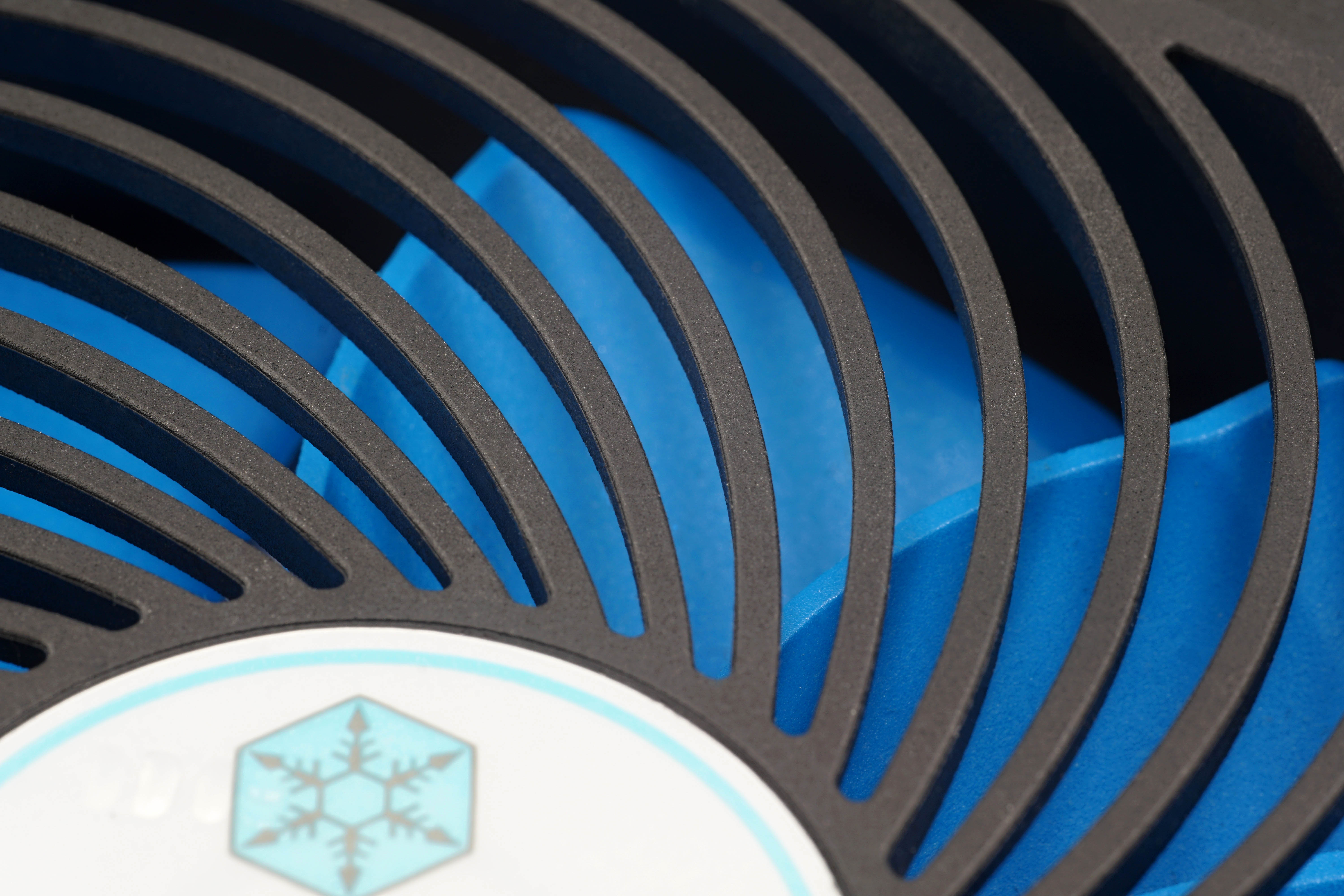
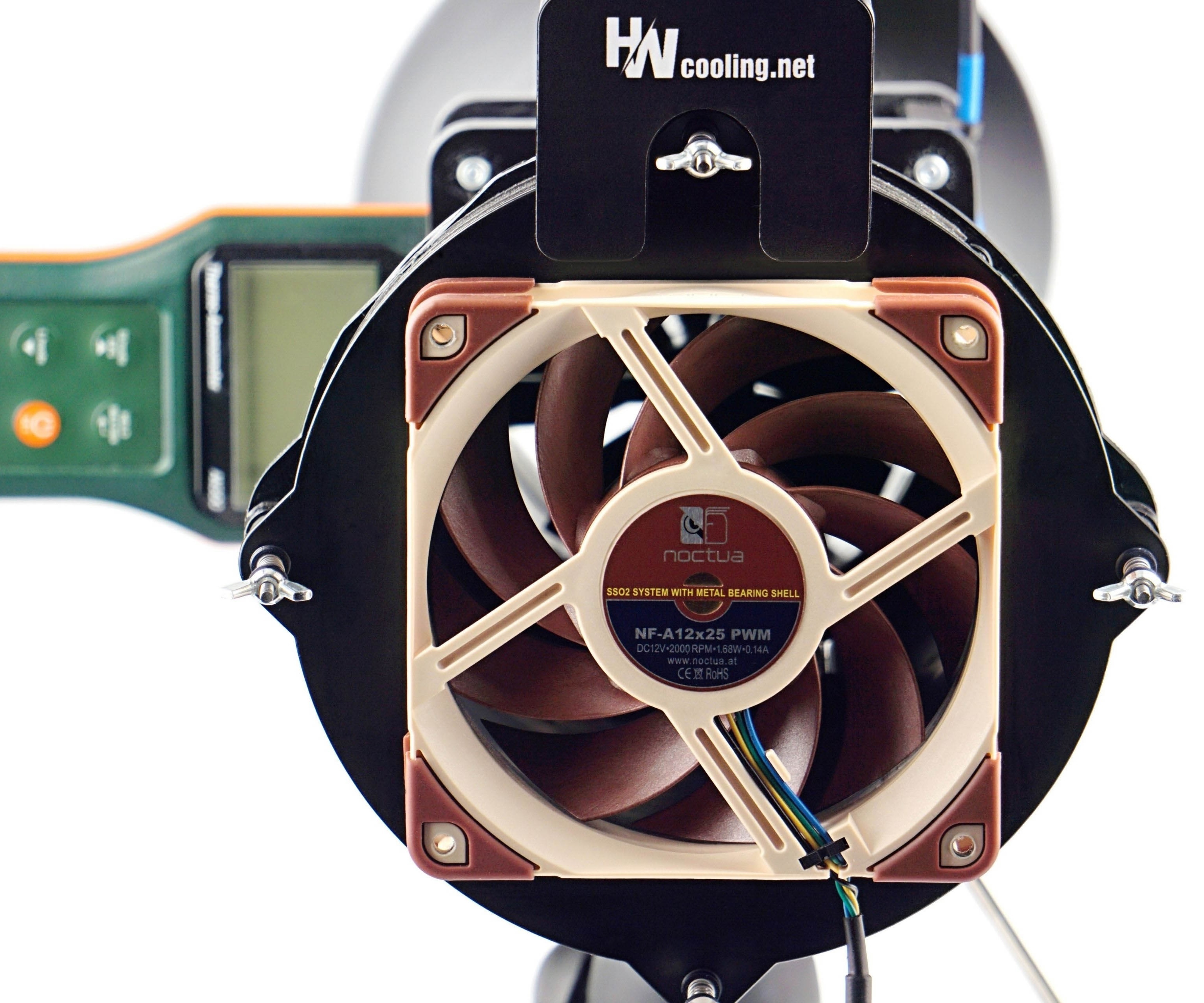
That’s probably enough for the theoretical part, let’s move on to the practical part and how the fan’s characteristics change after the grille is removed. Or rather after removing a large part of it. Of the 34 blades of the grille, 26 were removed for testing purposes. Eight pieces were left, these simulate the normal design of other fans.
You can see what the modified AP123 fan looks like in the header photo.
There is probably no need to expose the details for admiration. We haven’t paid much attention to the cosmetics and it’s a rough job with a soldering iron and refracting knife (to tweak imperfections). But the level of modification is accurate enough from a functional point of view, the rotor statics have been retained and the vibration hasn’t changed. The only difference is the grille and the worse (choppier) visuals.
So let’s get to those tests! You will find them traditionally in the following chapters of the article.
The first and still the only Asus fan that is on sale individually may be a good choice. But you can also get burnt. It depends on what you want to use it for. In the right context, it gives attractive results, and the impression of a very decent fan is spoiled mainly by pointless design details or sugar-coating the specs. Anyway, you can see that compared to the more ordinary fans from the last test, the Strix is a bit of a different class.
The basis of the methodology, the wind tunnel
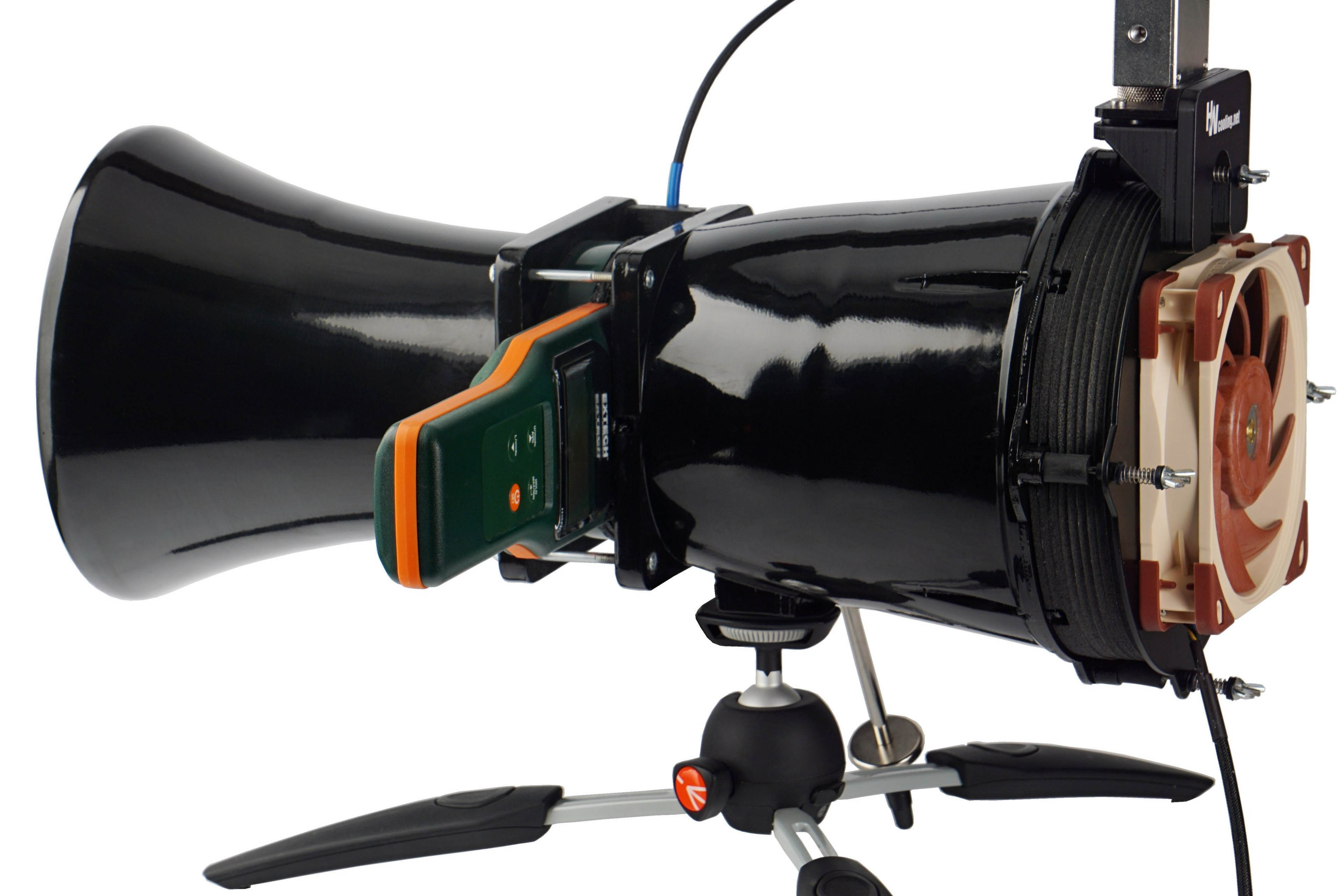
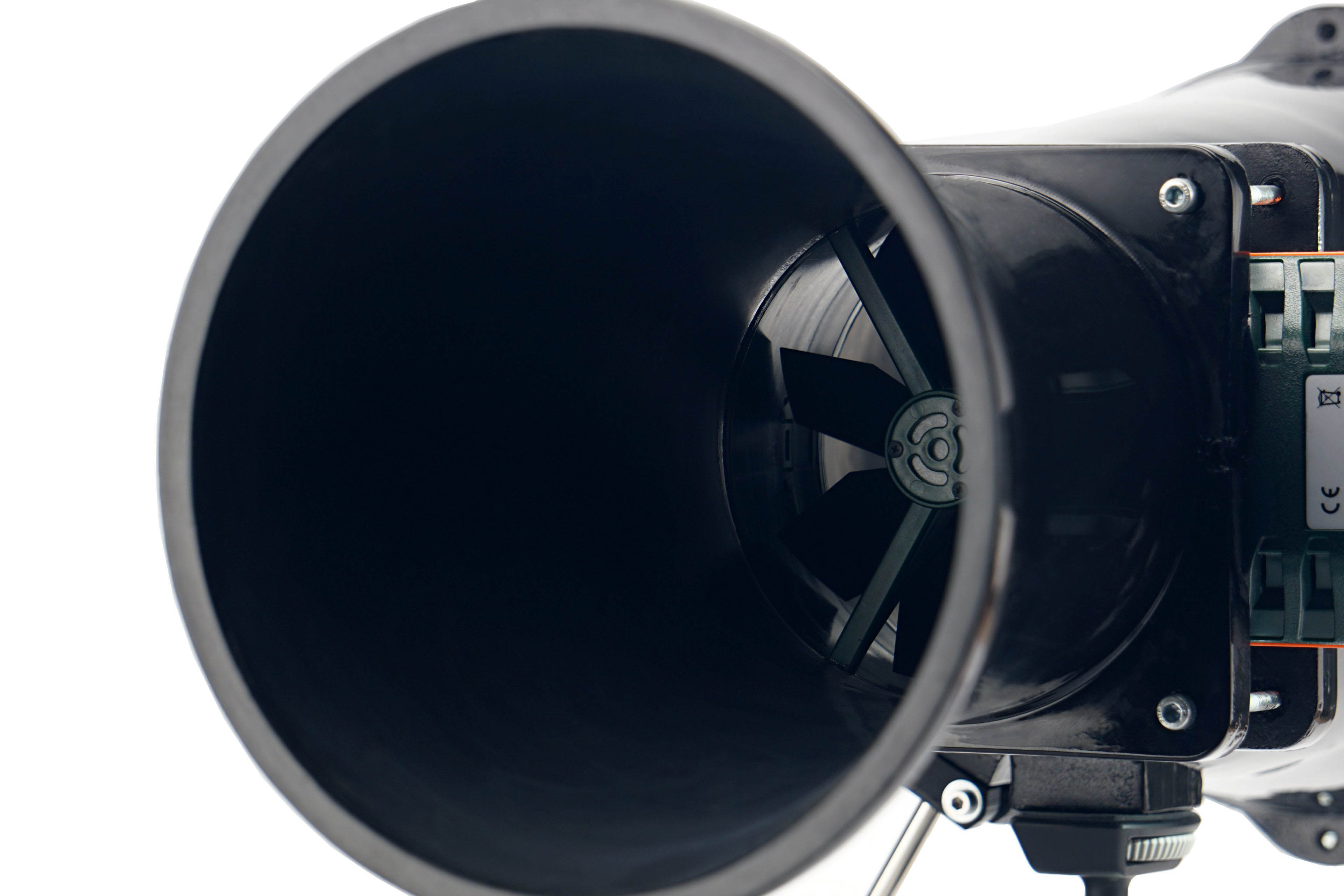
Before you start reading the methodology with all the details, take a look at the test tunnel as a whole. This is the heart of the whole system, to which other arteries are connected (manometer, vibrometer, powermeter, …). The only solid part of the tunnel from the measuring instruments is the anemometer.
The shape of the wind tunnel is inspired by the Venturi tube, which has long been used to measure the flow of liquids and gasses. The Venturi effect for wind speed measuring is also known from the aerospace industry. However, the design for measuring computer fans has its own specificities, which this proposal of ours reflects.
The individual parameters of the HWC wind tunnel for fan tests are the result of physical simulations and practical debugging. All the details (folds, material or finish used) have a rationale behind them and are designed this way for a specific reason. We will discuss the individual design details in turn in the description of the sub-variable measurements.
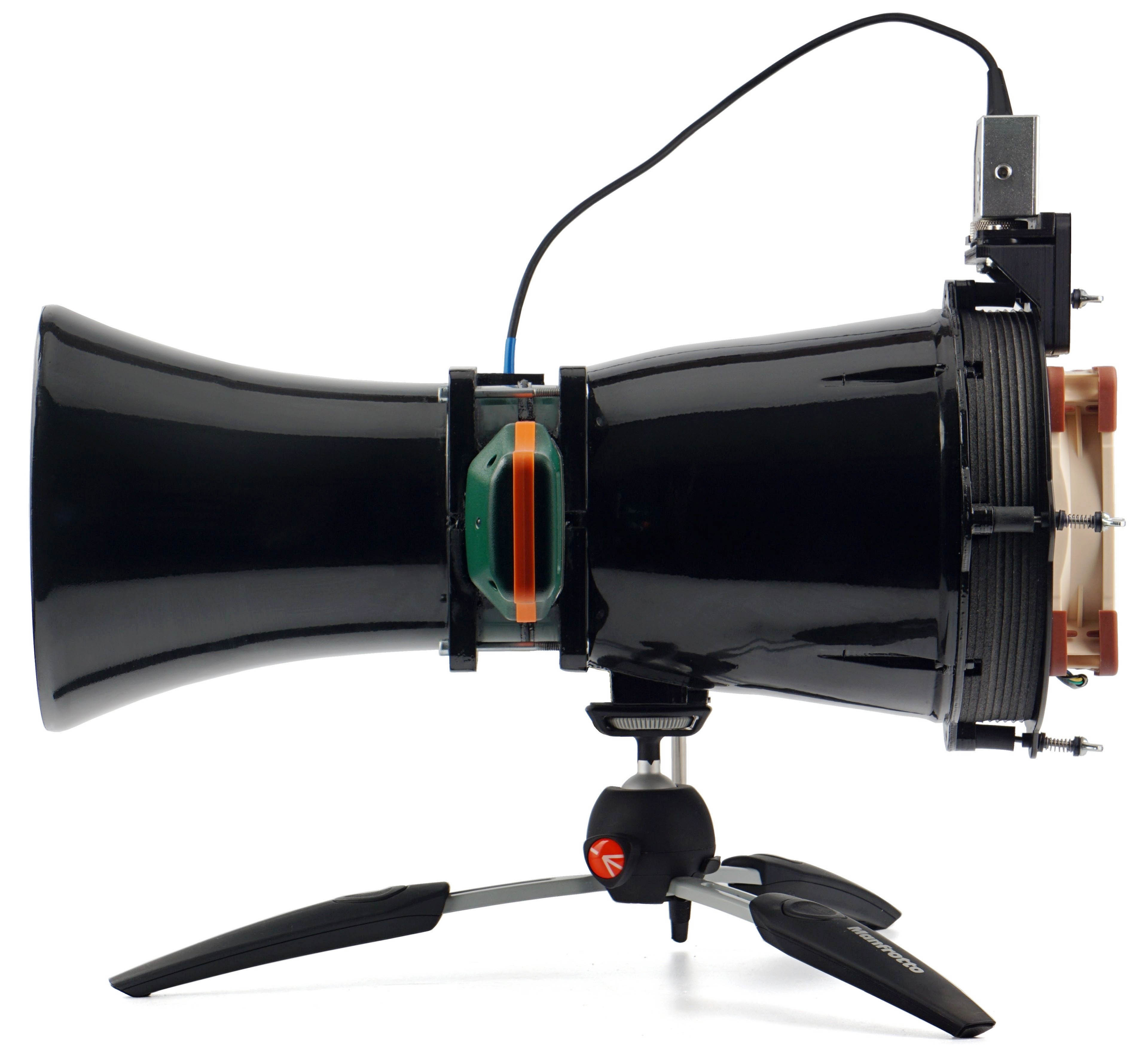
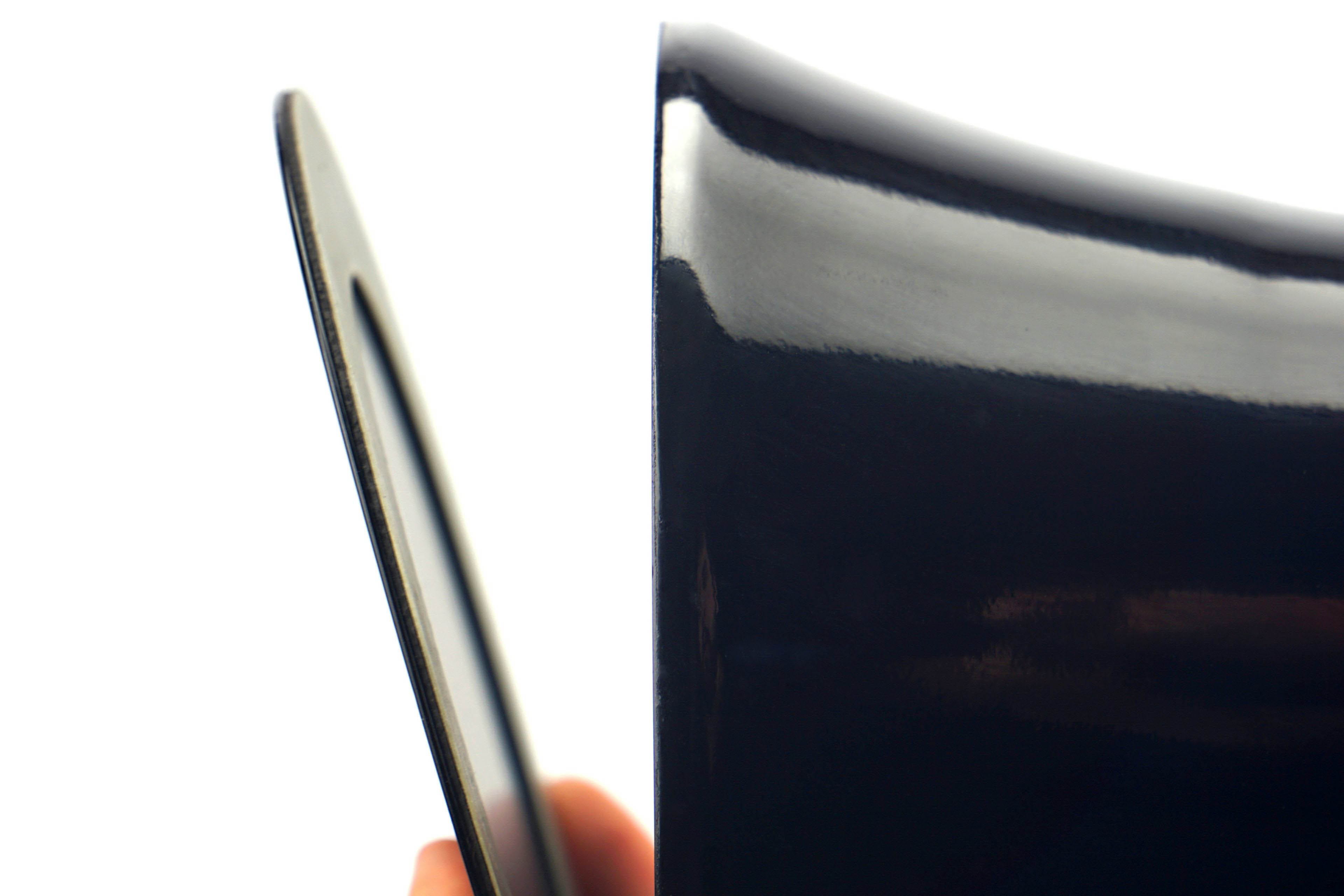
Now we will briefly elaborate on some things that do not fit thematically into the text of the following chapters. Namely, for example, that the skeleton of the wind tunnel is the work of a 3D printer (PLA). The rough print was, of course, then thoroughly machined by grinding, fusing, polishing and varnishing. Especially important is the smooth finish of the interior walls.
When joining the individual parts, the emphasis was on making sure that they fit together flawlessly, that they were sealed flawlessly (we will come back to this when we describe the test procedures for pressure measurement), but also that the joints were not loosened by use. Everything is disassemblable for servicing purposes, but it is ensured that the properties are maintained during use and, for example, even under the stress of vibration. The threads are secured with either lock nuts or thread-locking fluid. It depends on which is more suitable in which place.
When the wind tunnel is not in use, it is enclosed in a dust-tight chamber. In addition to the technical equipment and its correct storage, it is also important for objective outputs that all measuring instruments are calibrated according to the standard. Without this, it would be impossible to stand behind your results and rely on the manufacturers’ specifications. Calibration protocols are therefore an important part of the methodology. Testing is carried out at an ambient air temperature of 21–21.3 °C, humidity is approximately 45 % (± 2 %).
Fans come to us for testing in at least two pieces of the same model. If the deviations of any of the measured values are greater than 5 %, we also work with a third or fourth sample and the average value is formed by the results of the fans that came out the most similar and the differences between them fit under 5 %.
The first and still the only Asus fan that is on sale individually may be a good choice. But you can also get burnt. It depends on what you want to use it for. In the right context, it gives attractive results, and the impression of a very decent fan is spoiled mainly by pointless design details or sugar-coating the specs. Anyway, you can see that compared to the more ordinary fans from the last test, the Strix is a bit of a different class.
Static pressure measurement…
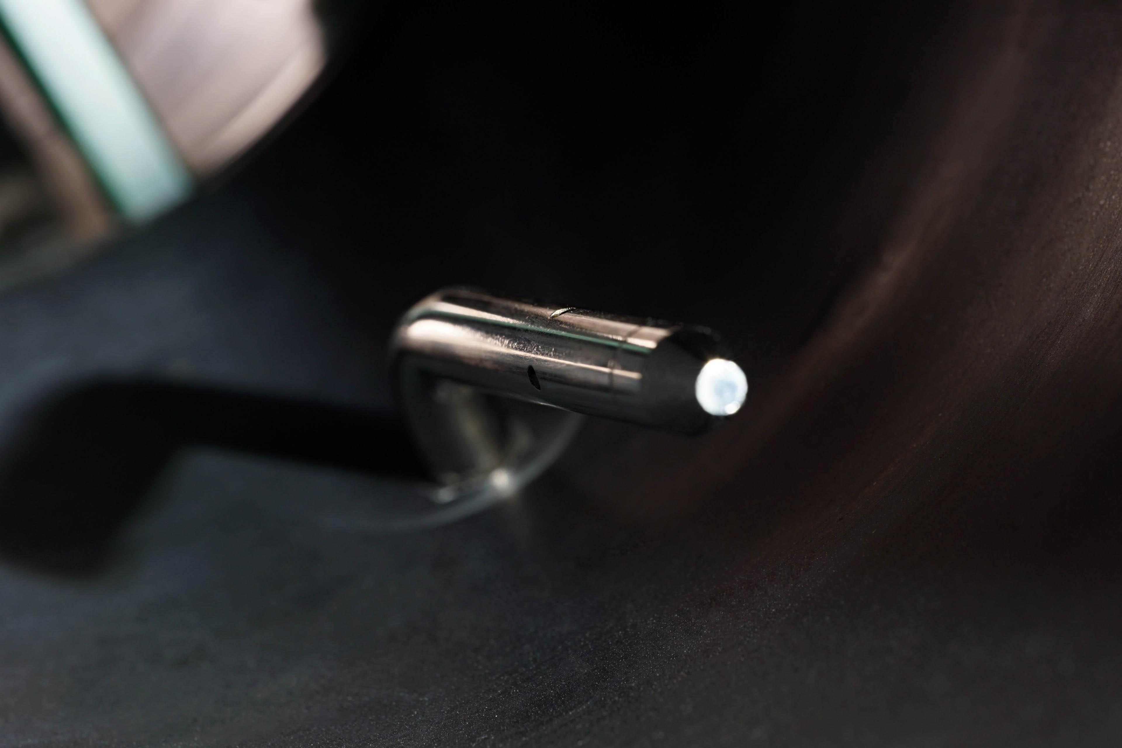
Finally, it is time to move further down the tunnel a bit. Just behind the fan is a static pressure sensing probe. Its position has been chosen with maximum measurement efficiency in mind. In other words, the sensors are placed at the points of highest pressure (although this is virtually the same everywhere in the unconstrained part of the tunnel).
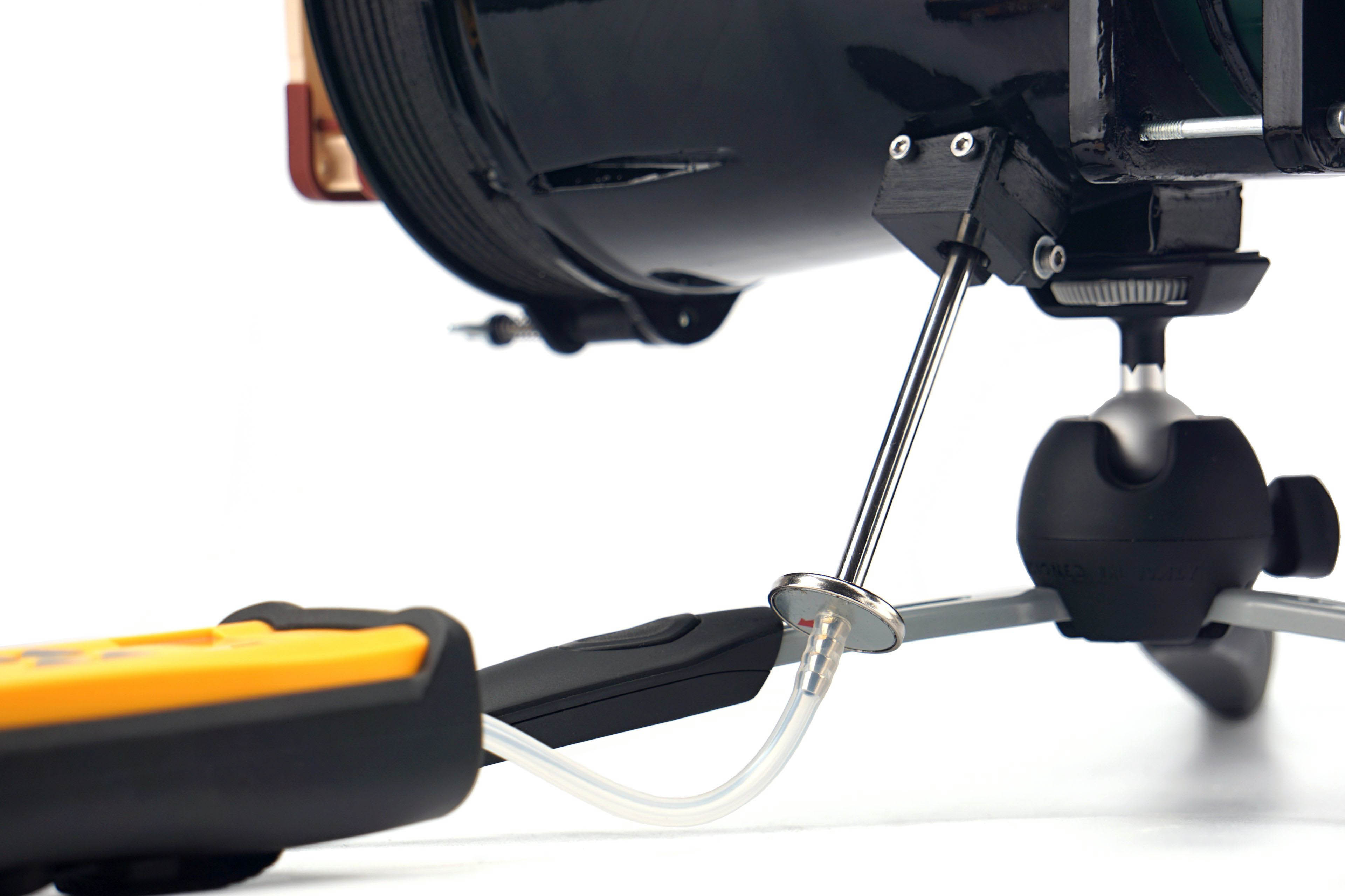
The Fieldpiece ASP2, which is connected to the Fieldpiece SDMN5 manometer, is used to measure the static pressure in the tunnel. The latter also allows measurements in millimetres of water column, but we measure in millibars. This is a more finely resolved base unit for this meter. And only from there we convert the measured values into mm H2O to allow easy comparison with what the manufacturers state.
While we wrote in the noise level measurements that our results could not be compared with the parameters, this is no longer the case. As long as the fan manufacturers do not embellish the parameters, they should give approximately the same pressure values as we did. The most significant deviations can only arise at the level of varying accuracy of the measuring instruments, but these are negligible percentages.
The greater the difference between the manufacturer’s claimed values and ours, the less the specifications correspond to reality. If the claimed values are significantly higher, it is certainly an intention to artificially give an advantage to the fans on the market. However, if the manufacturer quotes a lower pressure value than we do, it points to something else. Namely, a weaker tightness of the measuring environment. The less tight the tunnel is, the lower the pressure you naturally measure. This is one of the things we tuned for an extremely long time, but in the end we ironed out all the weak spots. Whether it’s the passage for the probe itself, the flanges around the anemometer, even the anemometer frame itself, which is made up of two parts, needed to be sealed in the middle. Finally, the flap at the tunnel outlet must also be perfectly tight. That’s because static pressure has to be measured in zero airflow.
But there is one thing that often lowers the pressure of the fans a bit. And that’s protruding anti-vibration pads in the corners or otherwise protruding corners. In other words, when the fan doesn’t fit perfectly to the mounting frame at the inlet, and there are small gaps around the perimeter, that also affects what you measure. But we have not gone into this because it is already a quality feature of the fan. In the same way, it will “stand out” and perform a bit weaker than it has the potential to do with better workmanship, even after application by the end user.
The first and still the only Asus fan that is on sale individually may be a good choice. But you can also get burnt. It depends on what you want to use it for. In the right context, it gives attractive results, and the impression of a very decent fan is spoiled mainly by pointless design details or sugar-coating the specs. Anyway, you can see that compared to the more ordinary fans from the last test, the Strix is a bit of a different class.
… and airflow
PWith airflow measurements, we can well explain why the test tunnel is shaped the way it is. It doesn’t consist of two parts just so that the “exhaust” can be conveniently clogged for pressure measurements. The anemometer (i.e. the wind speed measuring instrument) is held together by two parts, two formations, through the flanges.
The front part, at the beginning of which the fan is mounted, becomes steadily narrower and from about two thirds of the way through the cross-section is smaller than that of a 120 mm fan. The reason for this is that the cross-section of the anemometer is always smaller than that of the fans tested. The taper towards the anemometer fan is as smooth as could be chosen and the tunnel walls are smooth. This has minimized the occurrence of unnatural turbulence.
The difference between the cross section at the intake (fan under test) and at the constriction point (anemometer) also means a difference in dynamic pressure, the principles of the Venturi effect apply here. In order to avoid distortion at this level and to ensure that the fan airflow is not different from what it actually is, the Bernoulli equation must be applied to the measured values (for maximum accuracy, the calculation also takes into account the internal cross-sectional area of the anemometer, i.e. its inactive part ). After all this, it is again possible to confront our results with the paper parameters.
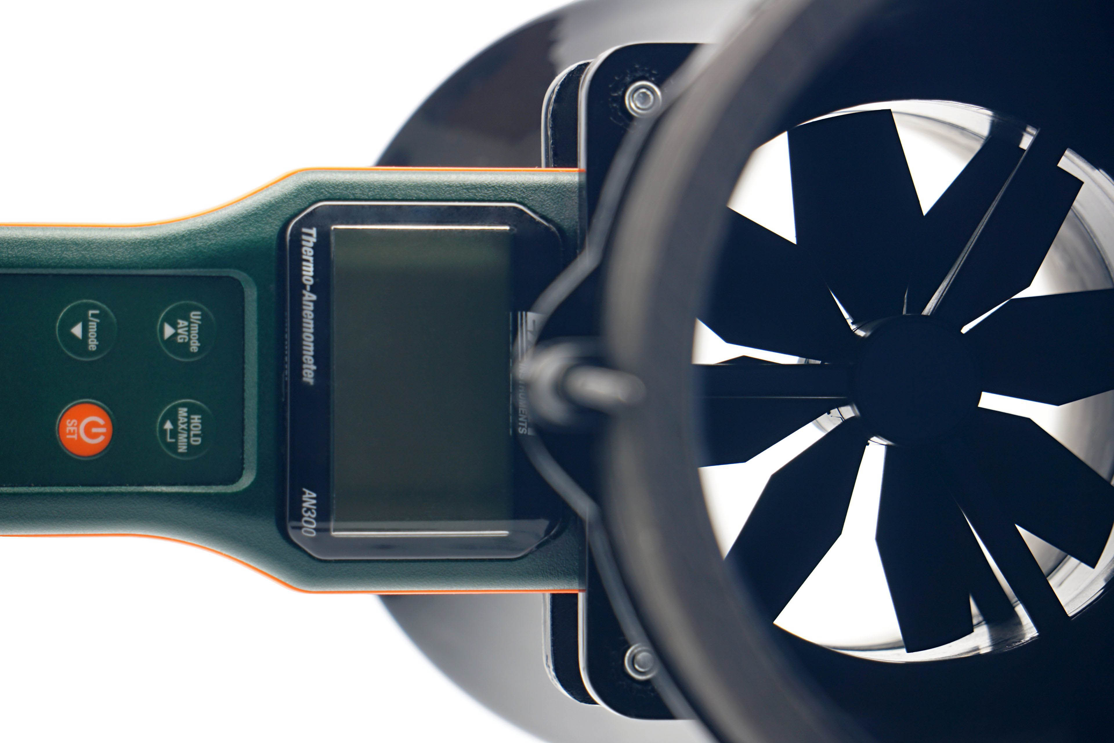
We use an Extech AN300 anemometer with a large 100 mm fan for the measurements. Its big advantage over other anemometers is that it is made for bidirectional sensing. This allows tests at different fan orientations. However, the “pull” position is more suitable or accurate for measurements, even though it may not seem so at first glance, but we’ll explain.
Here, we get to the second part of the tunnel, the part behind the anemometer. It is part of the whole device, mainly to allow a laminar flow of air to arrive at the rotor of the anemometer. Otherwise, uncontrolled side whirls would be reflected in the results, which are inconsistent with accurate measurements. Therefore, we will test the flow in the pull position. If anyone would like us to elaborate more on this topic, we can elaborate further at any time in the discussion below the article. Ask away. 🙂
In connection with the anemometer, we will return a little more to the noise measurements and to the setting of modes according to fixed noise levels. It may have occurred to you as you were reading that the anemometer fan is also a source of sound that needs to be filtered out when testing fans. For this reason, we insert a belay pad between the frame and the anemometer fan before each measurement and mode setting according to the fixed noise level. This, by the way, holds the anemometer fan also during static pressure measurements.
Every SilverStone Air Penetrator series fan includes an aerodynamic grille on the exhaust. This is firmly attached to the frame, but can be forcibly removed. The AP123 fan has gone through such a process and we will demonstrate the benefits of this grille. Whether it is good or bad cannot be noted briefly, but the way SilverStone communicates it to the public is again a bit unfortunate and misleading.
Results: Airflow w/o obstacles

Every SilverStone Air Penetrator series fan includes an aerodynamic grille on the exhaust. This is firmly attached to the frame, but can be forcibly removed. The AP123 fan has gone through such a process and we will demonstrate the benefits of this grille. Whether it is good or bad cannot be noted briefly, but the way SilverStone communicates it to the public is again a bit unfortunate and misleading.
Results: Static pressure w/o obstacles
Every SilverStone Air Penetrator series fan includes an aerodynamic grille on the exhaust. This is firmly attached to the frame, but can be forcibly removed. The AP123 fan has gone through such a process and we will demonstrate the benefits of this grille. Whether it is good or bad cannot be noted briefly, but the way SilverStone communicates it to the public is again a bit unfortunate and misleading.
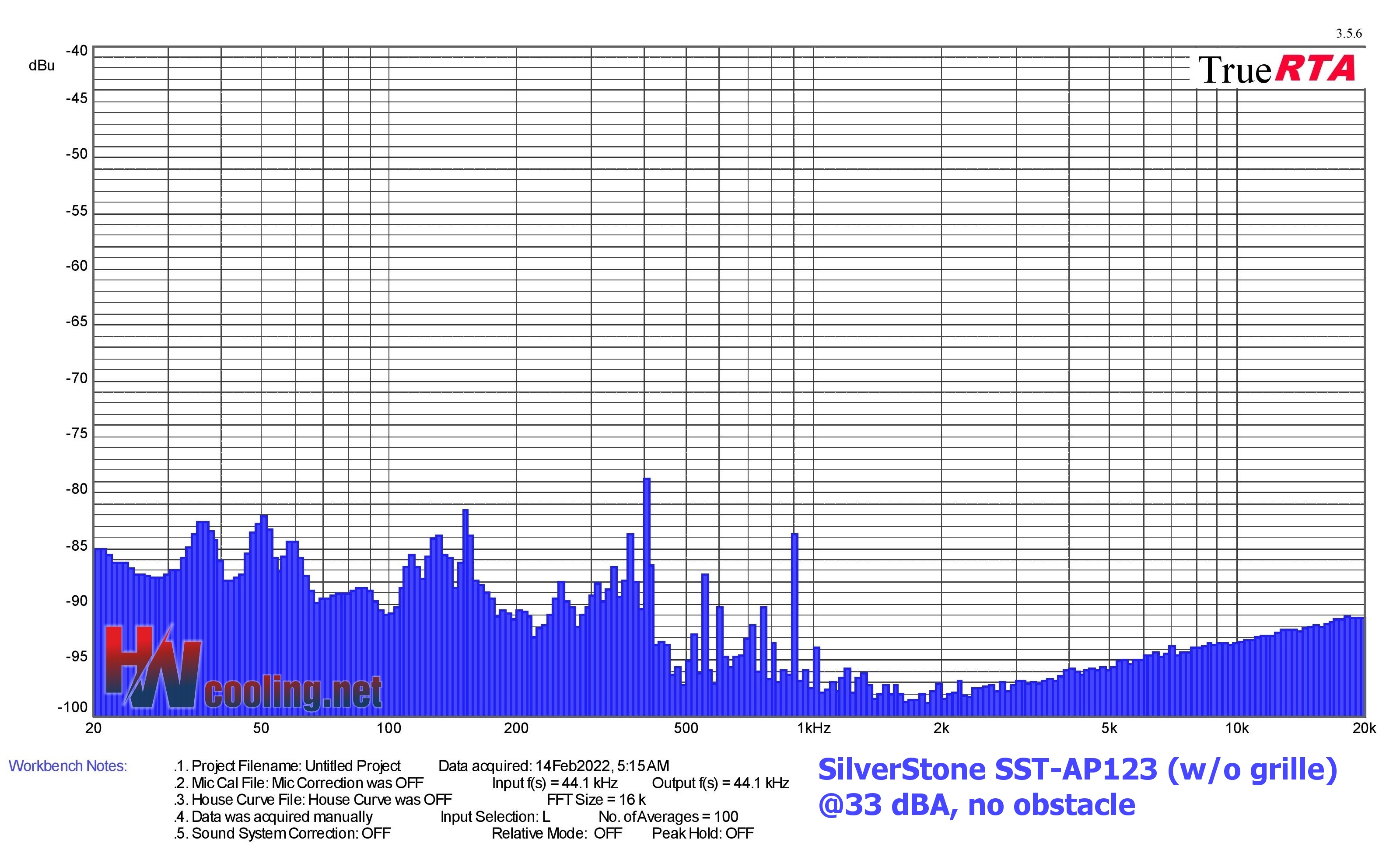
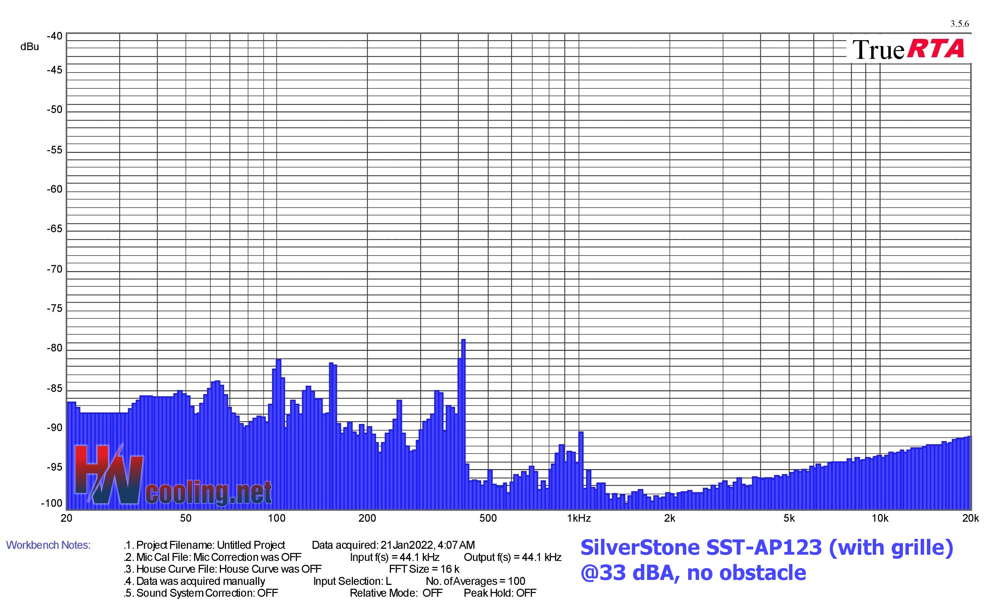
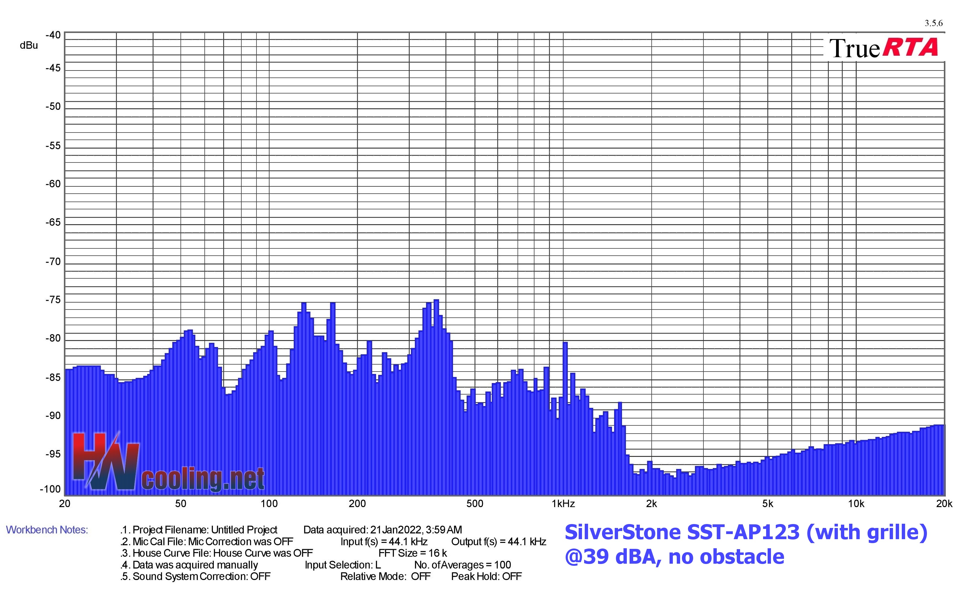
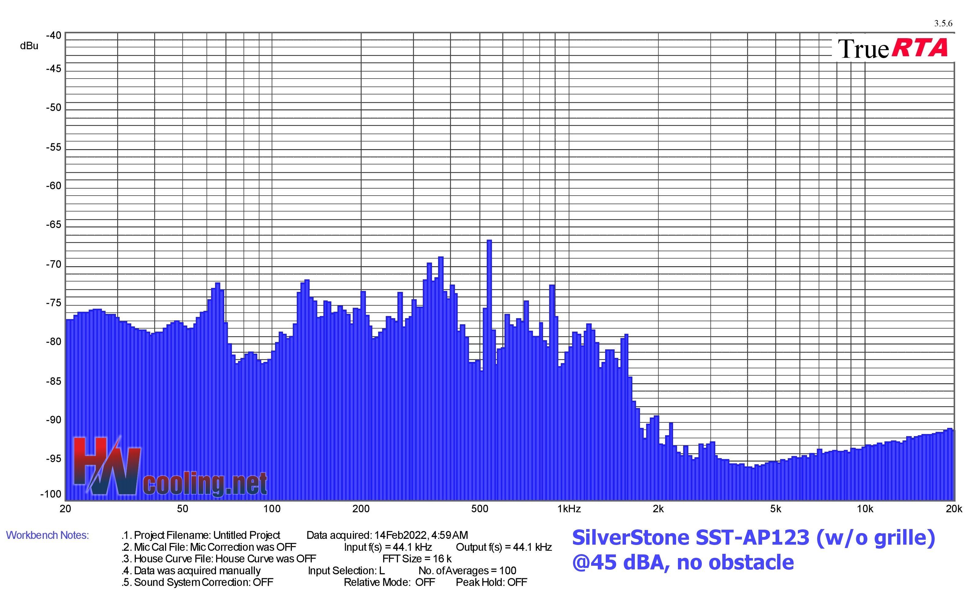
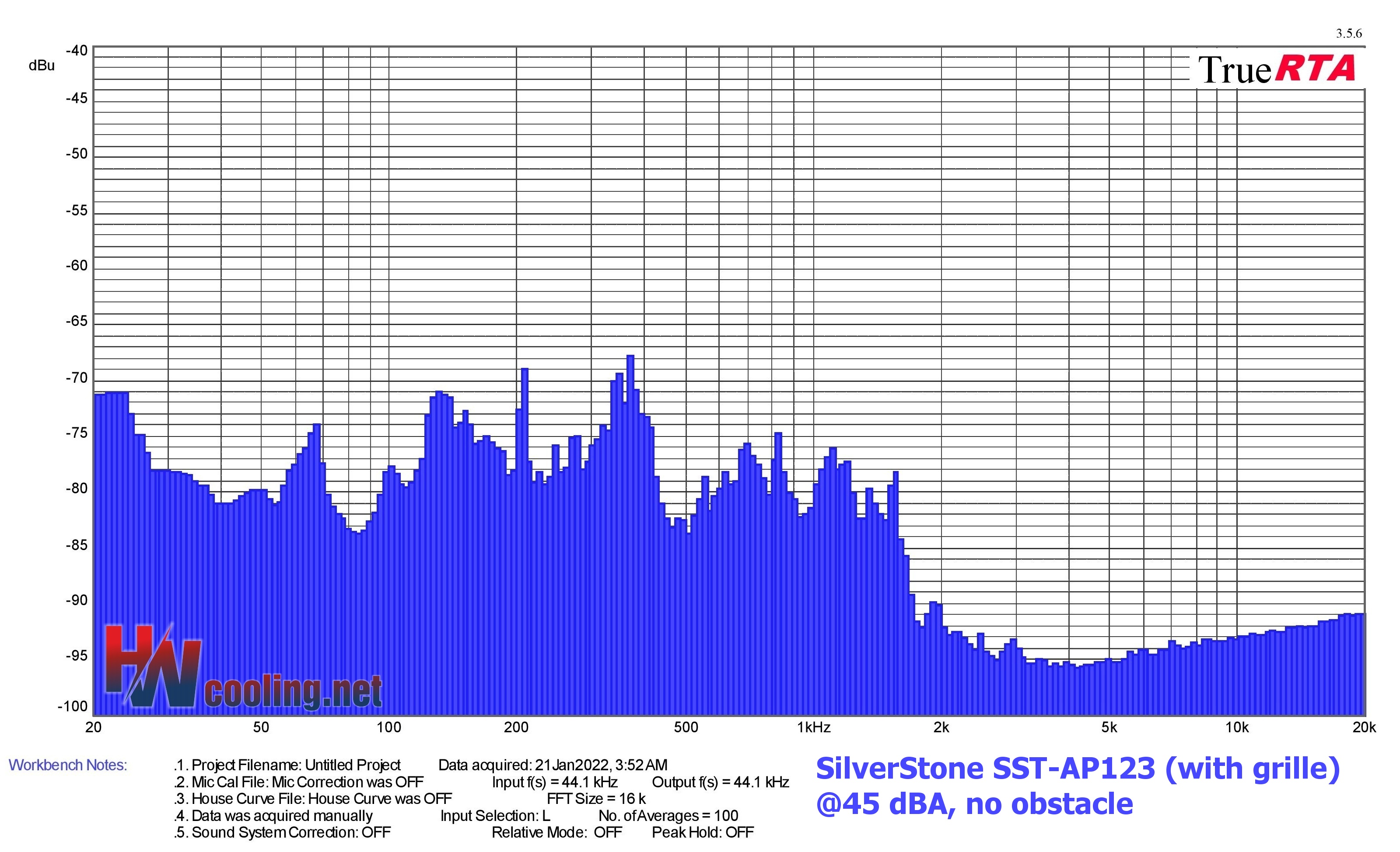
Results: Frequency response of sound w/o obstacles
Measurements are performed in the TrueRTA application, which records sound in a range of 240 frequencies in the recorded range of 20–20,000 Hz. For the possibility of comparison across articles, we export the dominant frequency from the low (20–200 Hz), medium (201–2,000 Hz) and high (2,001–20,000 Hz) range to standard bar graphs.
However, for an even more detailed analysis of the sound expression, it is important to perceive the overall shape of the graph and the intensity of all frequencies/tones. If you don’t understand something in the graphs or tables below, you’ll find the answers to all your questions in this article. It explains how to read the measured data below correctly.
Noise levels in the tables below -87 dBu (but watch out for the negative sign, -70 dBu is louder than -80 dBu) can be ignored. They are in fact extremely weak and always far below the limit of human perception, and are often defined by the “noise” of the measurement string. Therefore, do not take even the dominant frequencies within the treble band that exceed 12 kHz too much into account.
| Fan | Dominant sound freq. and noise level, no obstacle@33 dBA | NF-F12 PWM | NF-A15 PWM | ||||
| Low range | Mid range | High range | |||||
| Frequency [Hz] | Noise level [dBu] | Frequency [Hz] | Noise level [dBu] | Frequency [Hz] | Noise level [dBu] | ||
| SilverStone SST-AP123 (w/o grille) | 151,0 | -81,5 | 403,2 | -78,7 | 18245,6 | -91,1 | |
| SilverStone SST-AP123 (with grille) | SilverStone SST-AP123 | 100,8 | -81,2 | 415,0 | -78,6 | 19897,0 | -90,8 |
| Noctua NF-P12 redux-1700 PWM | 103,7 | -76,9 | 329,4 | -73,2 | 19330,5 | -90,9 | |
| SilentiumPC Fluctus 120 PWM | SilentiumPC Fluctus 120 PWM | 130,7 | -76,5 | 369,7 | -80,9 | 19897,0 | -91,0 |
| MSI MEG Silent Gale P12 | 50,4 | -81,7 | 369,7 | -81,0 | 19897,0 | -90,8 | |
| Asus ROG Strix XF120 | 50,4 | -80,2 | 329,4 | -76,2 | 19330,5 | -90,8 | |
| Akasa Vegas X7 | 123,4 | -77,0 | 369,7 | -83,3 | 19330,5 | -90,7 | |
| Reeven Coldwing 12 | 38,9 | -79,7 | 1317,5 | -84,0 | 19330,5 | -90,7 | |
| Reeven Kiran | 138,5 | -80,6 | 369,7 | -83,3 | 19330,5 | -90,8 | |
| SilentiumPC Sigma Pro 120 PWM | N/A | N/A | N/A | N/A | N/A | N/A | |
| SilentiumPC Sigma Pro Corona RGB 120 | 92,4 | -83,0 | 369,7 | -78,0 | 18780,2 | -90,8 | |
| SilverStone SST-AP121 | 47,6 | -77,5 | 261,4 | -86,4 | 19330,5 | -91,0 | |
| SilverStone SST-FQ121 | 31,3 | -87,5 | 1208,2 | -79,9 | 19330,5 | -90,9 | |
| Xigmatek XLF-F1256 | 41,8 | -69,7 | 213,6 | -77,3 | 19330,5 | -91,0 |

| Fan | Dominant sound freq. and noise level, no obstacle@39 dBA | NF-F12 PWM | NF-A15 PWM | ||||
| Low range | Mid range | High range | |||||
| Frequency [Hz] | Noise level [dBu] | Frequency [Hz] | Noise level [dBu] | Frequency [Hz] | Noise level [dBu] | ||
| SilverStone SST-AP123 (w/o grille) | 53,4 | -76,7 | 369,7 | 76,9 | 19330,5 | -91,0 | |
| SilverStone SST-AP123 (with grille) | SilverStone SST-AP123 | 164,7 | -75,1 | 369,7 | -74,7 | 19330,5 | -90,9 |
| Noctua NF-P12 redux-1700 PWM | 146,7 | -68,0 | 329,4 | -66,7 | 18245,6 | -91,1 | |
| SilentiumPC Fluctus 120 PWM | 190,3 | -69,2 | 380,5 | -68,8 | 19897,0 | -90,9 | |
| MSI MEG Silent Gale P12 | 23,1 | -73,5 | 380,5 | -73,3 | 18780,2 | -90,9 | |
| Asus ROG Strix XF120 | 130,7 | -70,9 | 369,7 | -75,2 | 19330,5 | -91,0 | |
| Akasa Vegas X7 | 127,0 | -77,8 | 369,7 | -76,1 | 19330,5 | -90,9 | |
| Reeven Coldwing 12 | 160,0 | -74,0 | 369,7 | -76,8 | 19330,5 | -90,9 | |
| Reeven Kiran | 184,9 | -75,2 | 369,7 | -75,2 | 17726,2 | -89,8 | |
| SilentiumPC Sigma Pro 120 PWM | 97,9 | -81,7 | 369,7 | -78,1 | 2635,0 | -86,2 | |
| SilentiumPC Sigma Pro Corona RGB 120 | 20,3 | -67,8 | 380,5 | -77,3 | 2487,1 | -85,6 | |
| SilverStone SST-AP121 | 103,7 | -76,2 | 339,0 | -73,4 | 2031,9 | -86,5 | |
| SilverStone SST-FQ121 | 138,5 | -75,2 | 1208,2 | -71,1 | 18780,2 | -90,9 | |
| Xigmatek XLF-F1256 | 190,3 | -77,1 | 761,1 | -75,5 | 19897,0 | -91,1 |
| Fan | Dominant sound freq. and noise level, no obstacle@45 dBA | NF-F12 PWM | NF-A15 PWM | ||||
| Low range | Mid range | High range | |||||
| Frequency [Hz] | Noise level [dBu] | Frequency [Hz] | Noise level [dBu] | Frequency [Hz] | Noise level [dBu] | ||
| SilverStone SST-AP123 (w/o grille) | 130,7 | -71,8 | 538,2 | -66,7 | 2215,8 | -90,1 | |
| SilverStone SST-AP123 (with grille) | SilverStone SST-AP123 | 130,7 | -70,9 | 369,7 | -67,7 | 19897,0 | -90,9 |
| Noctua NF-P12 redux-1700 PWM | 184,9 | -62,2 | 369,7 | -67,0 | 19897,0 | -91,1 | |
| SilentiumPC Fluctus 120 PWM | silentiumpc-fluctus-120-pwm-t3 | 25,6 | -69,6 | 239,7 | -62,0 | 2957,7 | -90,0 |
| MSI MEG Silent Gale P12 | 28,3 | -73,5 | 380,5 | -71,0 | 2487,1 | -85,9 | |
| Asus ROG Strix XF120 | 23,1 | -62,9 | 369,7 | -71,7 | 2347,5 | -89,1 | |
| Akasa Vegas X7 | N/A | N/A | N/A | N/A | N/A | N/A | |
| Reeven Coldwing 12 | 195,8 | -68,3 | 380,5 | -71,3 | 2031,9 | -90,0 | |
| Reeven Kiran | 130,7 | -73,1 | 219,8 | -70,2 | 17726,2 | -89,4 | |
| SilentiumPC Sigma Pro 120 PWM | 138,5 | -70,0 | 1522,2 | -71,9 | 2560,0 | -82,9 | |
| SilentiumPC Sigma Pro Corona RGB 120 | 190,3 | -70,5 | 369,7 | -66,5 | 2416,3 | -82,4 | |
| SilverStone SST-AP121 | 130,7 | -66,8 | 439,7 | -66,1 | 2347,5 | -90,9 | |
| SilverStone SST-FQ121 | 127,0 | -71,2 | 369,7 | -66,5 | 2031,8 | -81,4 | |
| Xigmatek XLF-F1256 | 130,7 | -71,5 | 239,7 | -60,9 | 18780,2 | -91,1 |
Every SilverStone Air Penetrator series fan includes an aerodynamic grille on the exhaust. This is firmly attached to the frame, but can be forcibly removed. The AP123 fan has gone through such a process and we will demonstrate the benefits of this grille. Whether it is good or bad cannot be noted briefly, but the way SilverStone communicates it to the public is again a bit unfortunate and misleading.
Conclusion
We’ll start our assessment of the benefits of the SilverStone aerodynamic grille with a simple question. Why don’t other manufacturers use it in their designs? Firstly, because in normal practice it degrades rather than improves cooling efficiency. This grille reduces airflow by 15-84%. The lower the speed, the more intense the deterioration. The dynamic pressure behind the rotor becomes weaker as the speed decreases and it becomes more and more difficult for the fan to overcome the obstacle in the form of the grille.
Remarkably, the grille does not increase the noise level. Without the grille, we even measured 0.4 dBA more noise at maximum speed. The grille is, of course, an obstacle that increases the mechanical resistance (because of which the noise increases), but on the other hand it modifies the character of the flow. This is still turbulent, but the flow behind the grille is nevertheless more laminar (quieter), although this (laminarization) is not encouraged too much in order not to degrade the characteristics for use on heatsinks. This is also why the individual blades of the grille are curved, thus encouraging turbulent flow.
While the airflow is lower with the grille at all times (than without the grille), in the 1050–1350 rpm spectrum, higher static pressure is achieved with it. At other, higher or lower speeds, the static pressure is otherwise always slightly lower.

The grille doesn’t affect the frequency characteristic of the sound much either, especially at the lower speeds of the fixed levels of 33 and 39 dBA, the shape of the spectrographs is like through a photocopier. Larger but still negligible differences are only in the 45 dBA mode. Without the grille, the dominant frequency in the lower band (131 Hz) is a hair weaker (less loud).
The dominant frequency in the mid-band, on the other hand, is stronger, and also different, 150 Hz higher (538 Hz) than it is in the original composition with the grille. The frequencies around 2 kHz are also slightly stronger without the grille. However, these are subtle shades and you won’t notice the change in acoustics with ordinary ears. SilverStone has tuned this well, even though the individual grille blades have squared edges.
The biggest differences are in the intensity of the flow, i.e. the volume of air pumped. In this respect, the grille is detrimental and the flow trajectory can be bent in a much more reasonable way than this. Losslessly, using tunnels. And it doesn’t have to be anything complicated either. To cool the GPU (and its VRM) more efficiently, just make a cardboard canopy, supported on one side by the fan frame and on the other by the backplate of the graphics card itself. In addition to higher airflow for the cooler, this will also give you higher pressure for the passive components. However, this may not provide better cooling.
Remember the tests of the Adata XPG Storm cooler, which heated the SSD more in active mode than in passive mode, despite properly optimized system cooling.
Our thanks goes to reader Mino_85, for the idea for this article.
English translation and edit by Jozef Dudáš