


Methodology: How we measure power draw
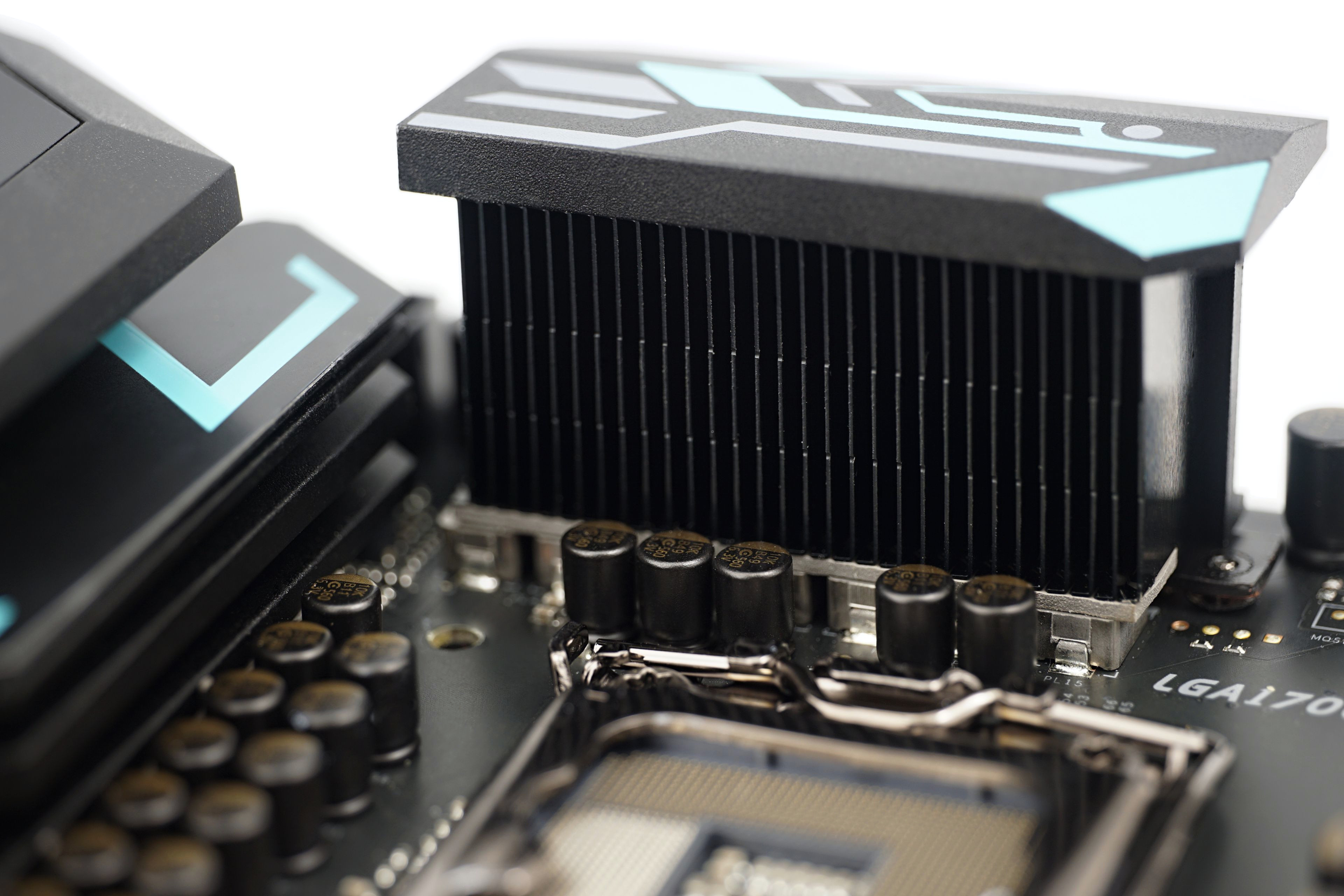
Most motherboards from the same classes look pretty much the same. While they differ in color scheme and heatsink shape, the layout, features, and overall operation (including power management) are like a carbon copy. The Biostar B660GTA goes upstream in many ways and presents an attractive option for those users who always find something lacking on boards in this price range.
Methodology: How we measure power draw
Motherboard “power draw” analysis is an extremely attractive topic if approached methodically. What does it mean? Measuring the electric current and voltage directly on the wiring that powers the motherboard. Naturally, the processor, or the processor power supply, has the most significant draw, which we measure separately – just as in processor tests.
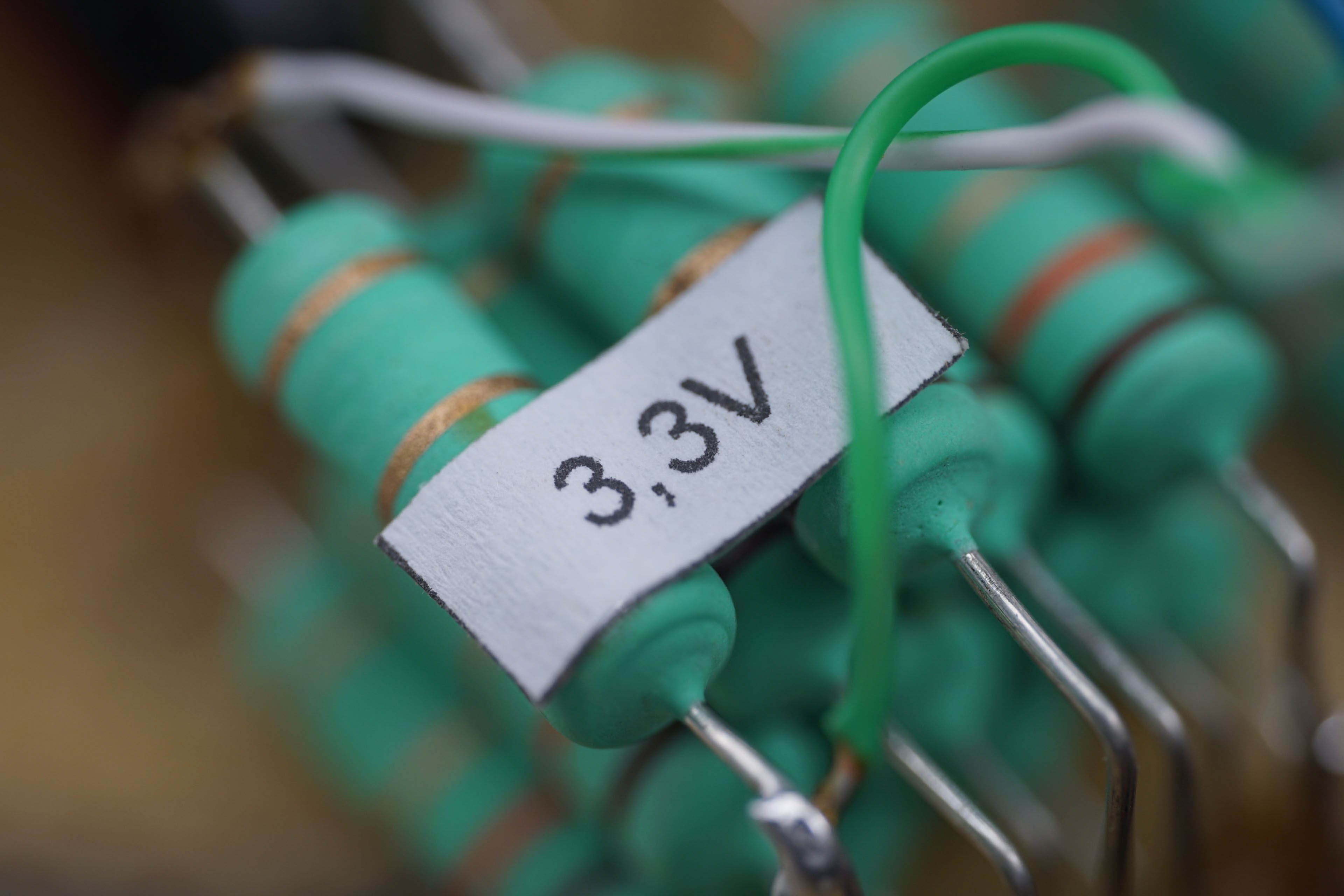
In addition to the EPS cable, there is also a 24-pin ATX cable with multiple voltages, which is good to keep track of. The key ones are +3.3 V (from which the chipset is typically powered), +5 V (memory) and +12 V, from which the PCI Express slots are powered, and the biggest draw will be in the case of our test configuration on the graphics card. All of these wires are closely monitored. But then within the ATX connector there are also a few relatively unimportant branches that are no longer even used in modern computers (that is, -12 V and -5 V) or are relatively unimportant in terms of power draw. For example +5 VSB (power supply for USB or ARGB lighting even when the computer is switched off; this can usually be switched off in the BIOS) or PG (Power Good), which is only informative and during operation it is only “an also-run”. These branches (-12 V, -5 V, +5 VSB and PG) always have only one wire and often with a smaller cross section, which is also a sign of always very low power draw.
The 24-pin wires on which we measure the power draw are always connected in parallel and are at least in pairs (+12 V) or greater in number. For example, the +3.3 V branch uses four conductors to increase the cross section and the +5 V branch has up to five. However, this branch is quite oversized from today’s point of view, as historically it was intended to power more HDDs or their logical part (+12 V is used for the mechanical part).
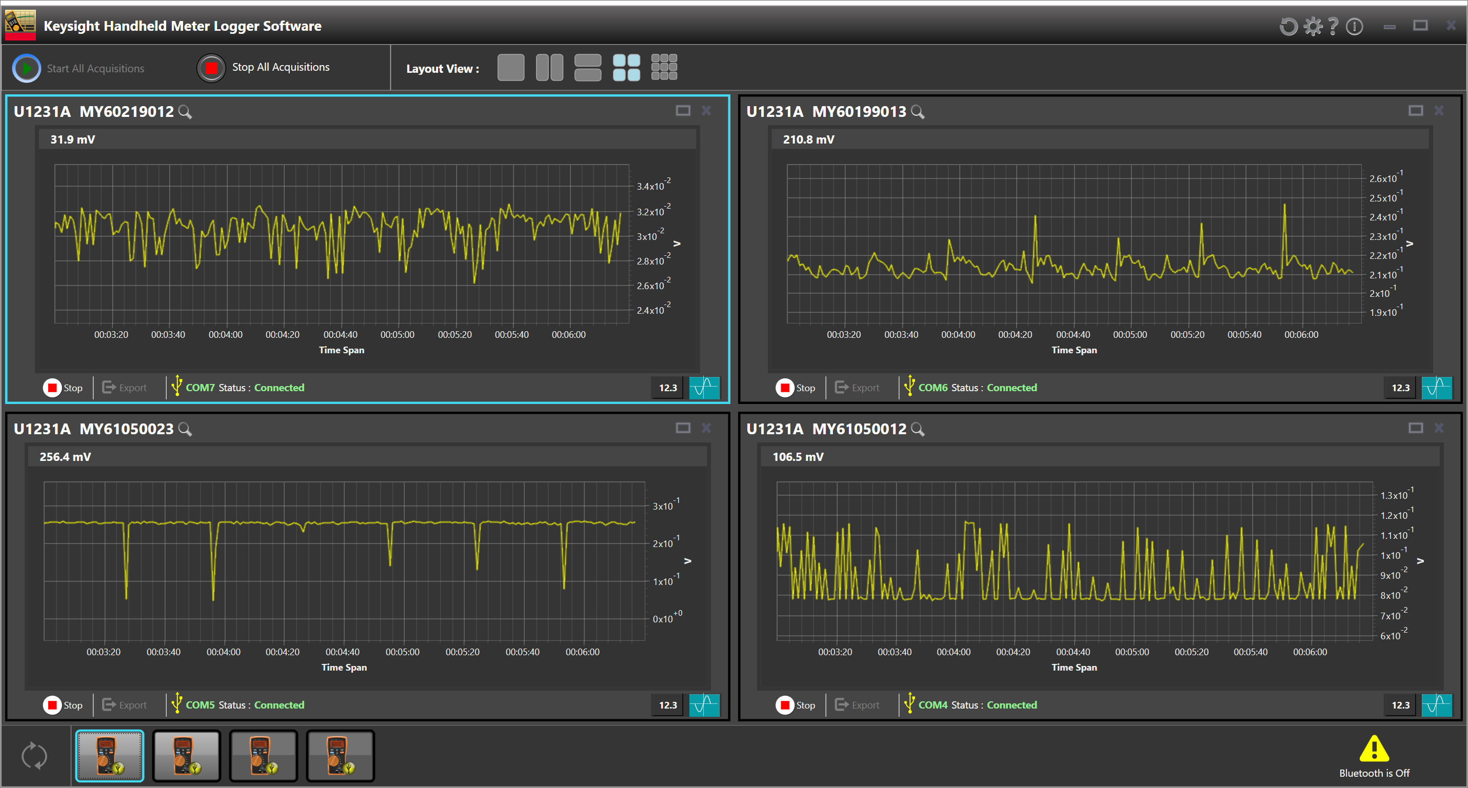
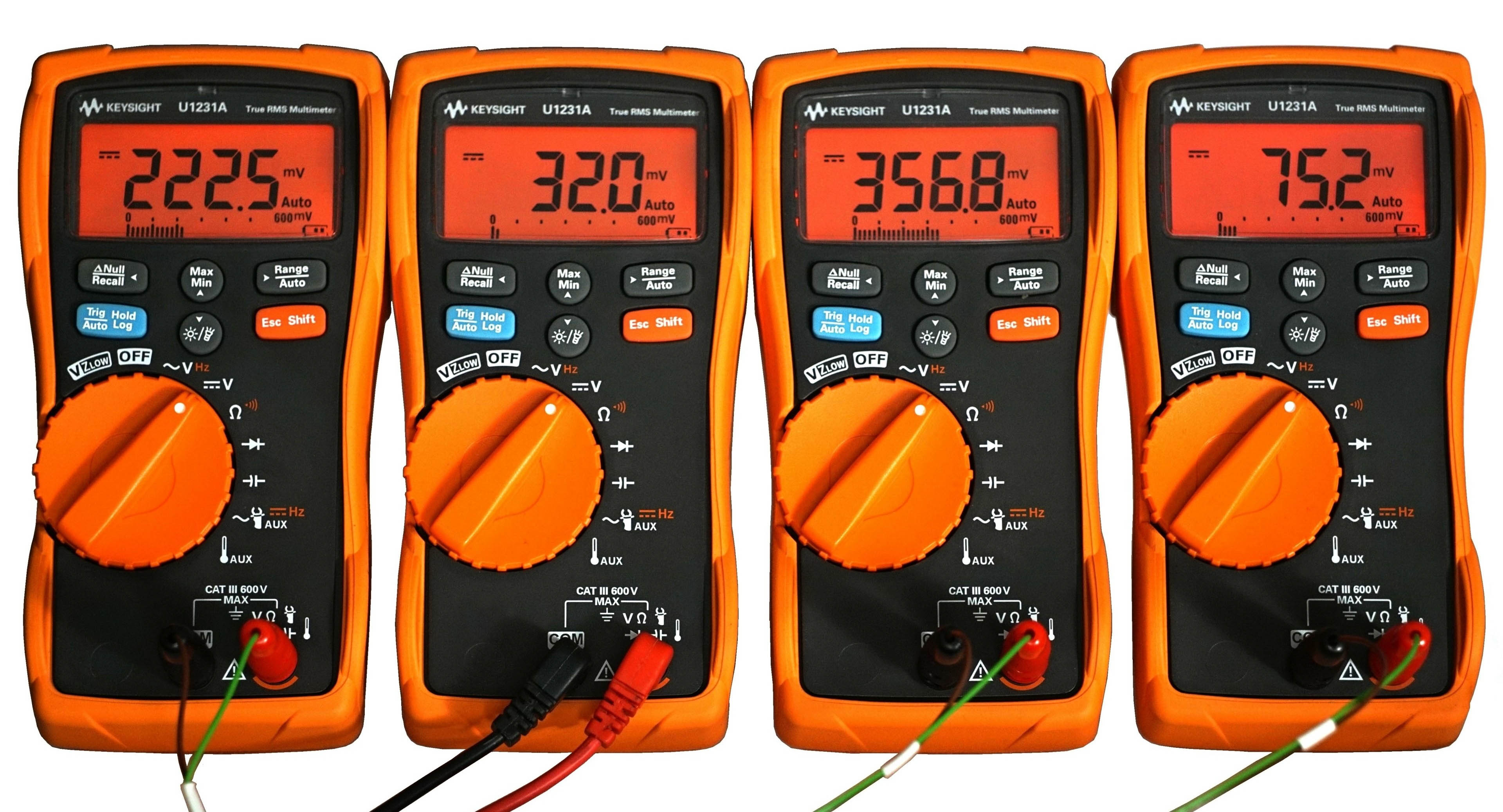
We use a shunt of our own making to measure the draw from the 24-pin. This is built on a very simple principle and consists of very low-value resistors. The value is set so low that the voltage drop is not higher than the ATX standard. Based on the known resistance in the circuit and the voltage drop across it, we can calculate the electric current, and once the output is substituted into the known formula to calculate the power, the mathematics is easy. Samples during the course of the tests are recorded using the Keysight U1231A multimeter array via a service application that allows the recorded data to be exported in CSV. And that’s the final destination for creating line graphs or counting averages (into bar interactive graphs). That’s how simple it is.
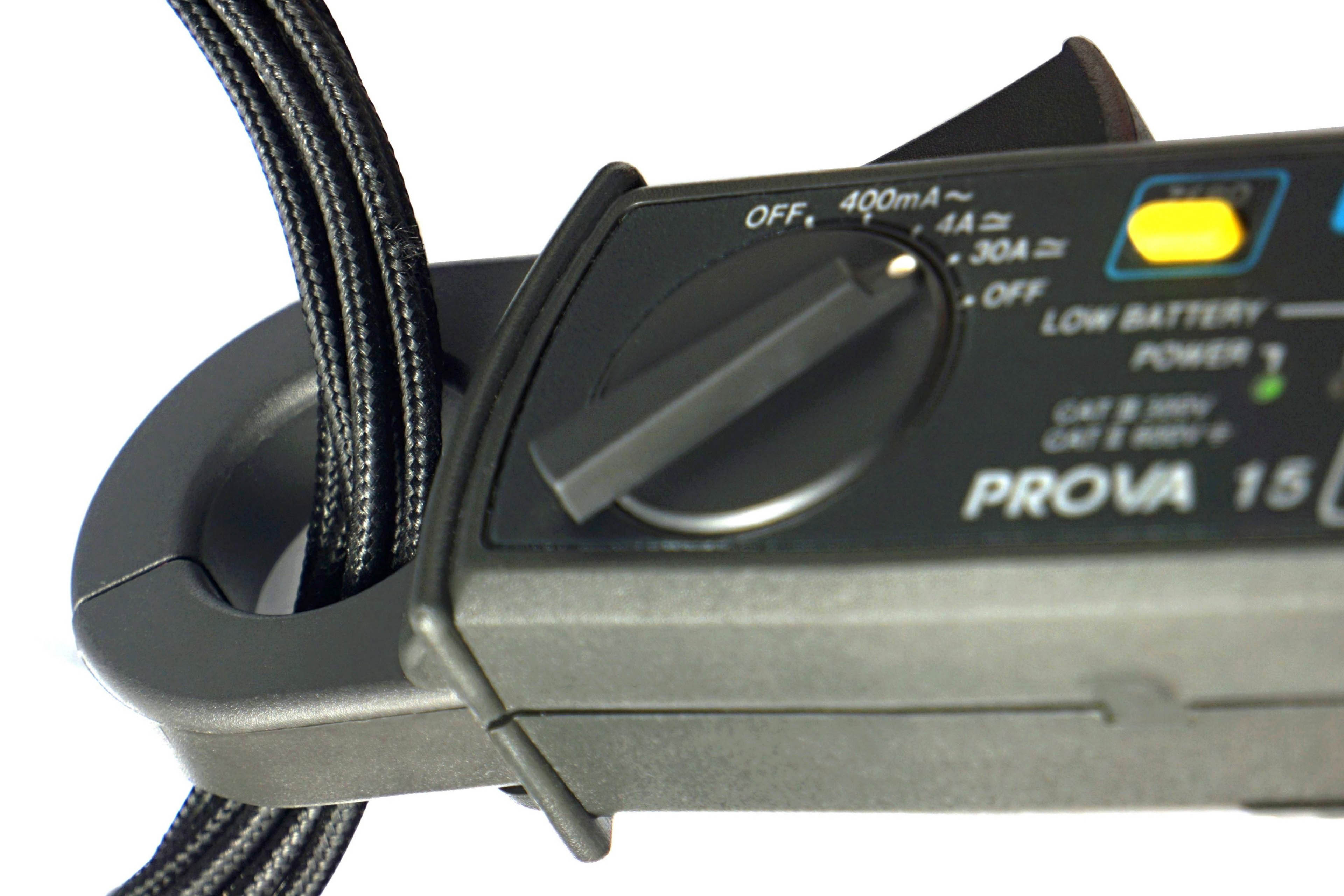
For completeness it is good to add that the current clamps for measuring the current draw from the EPS cables (power supply to the processor) are Prova 15. These will soon be replaced by a more practical solution for desktop use, namely a similar shunt we use for the ATX connector. The only reason it is not yet in circulation is its more complex design (as it has to account for very high currents) and the need for thorough testing, which we are yet to get to. Since we place a high emphasis on accuracy in our tests, all measuring devices are properly calibrated.
- Contents
- Biostar B660GTA in detail
- What it looks like in the BIOS
- Methodology: Performance tests
- Methodology: How we measure power draw
- Methodology: Temperature and frequency measurements
- Test setup
- 3DMark
- Borderlands 3
- F1 2020
- Metro Exodus
- Shadow of the Tomb Raider
- Total War Saga: Troy
- PCMark and Geekbench
- Web performance
- 3D rendering: Cinebench, Blender, ...
- Video 1/2: Adobe Premiere Pro
- Video 2/2: DaVinci Resolve Studio
- Graphics effects: Adobe After Effects
- Video encoding
- Audio encoding
- Photos: Adobe Photoshop, Affinity Photo, ...
- (De)compression
- (De)cryption
- Numerical computing
- Simulations
- Memory and cache tests
- M.2 (SSD) slots speed
- USB ports speed
- Ethernet speed
- Power draw curve (EPS + ATX connector) w/o power limits
- Power draw curve (EPS + ATX connector) with Intel’s power limits
- Total power draw (EPS + ATX connector)
- Achieved CPU clock speed
- CPU temperatures
- VRM temperatures – thermovision of Vcore and SOC
- SSD temperatures
- Chipset temperatures (south bridge)
- Conclusion


Super awesome review, very complete