


Clockwise rotation fans are quite a rarity, you don’t normally come across them. However, Scythe, for example, makes such models and for good reason. Why not take it the other way around? In terms of standalone operation, of course, it doesn’t matter. In series, in the position of the second fan, it is possible to achieve higher cooling performance on CPU coolers compared to using fans with the same direction of rotation.
33 dBA or 33 dBA
The noise level, given as a single dBA value, is good for quick reference, but it doesn’t give you an idea of exactly what the sound sounds like. That’s because it averages a mix of noise levels of all frequencies of sound. One fan may disturb you more than the other, even though they both reach exactly the same dBA, yet each is characterized by different dominant (louder) frequencies. To analyze thoroughly with an idea of the “color” of the sound, it is essential to record and assess noise levels across the entire spectrum of frequencies that we perceive.

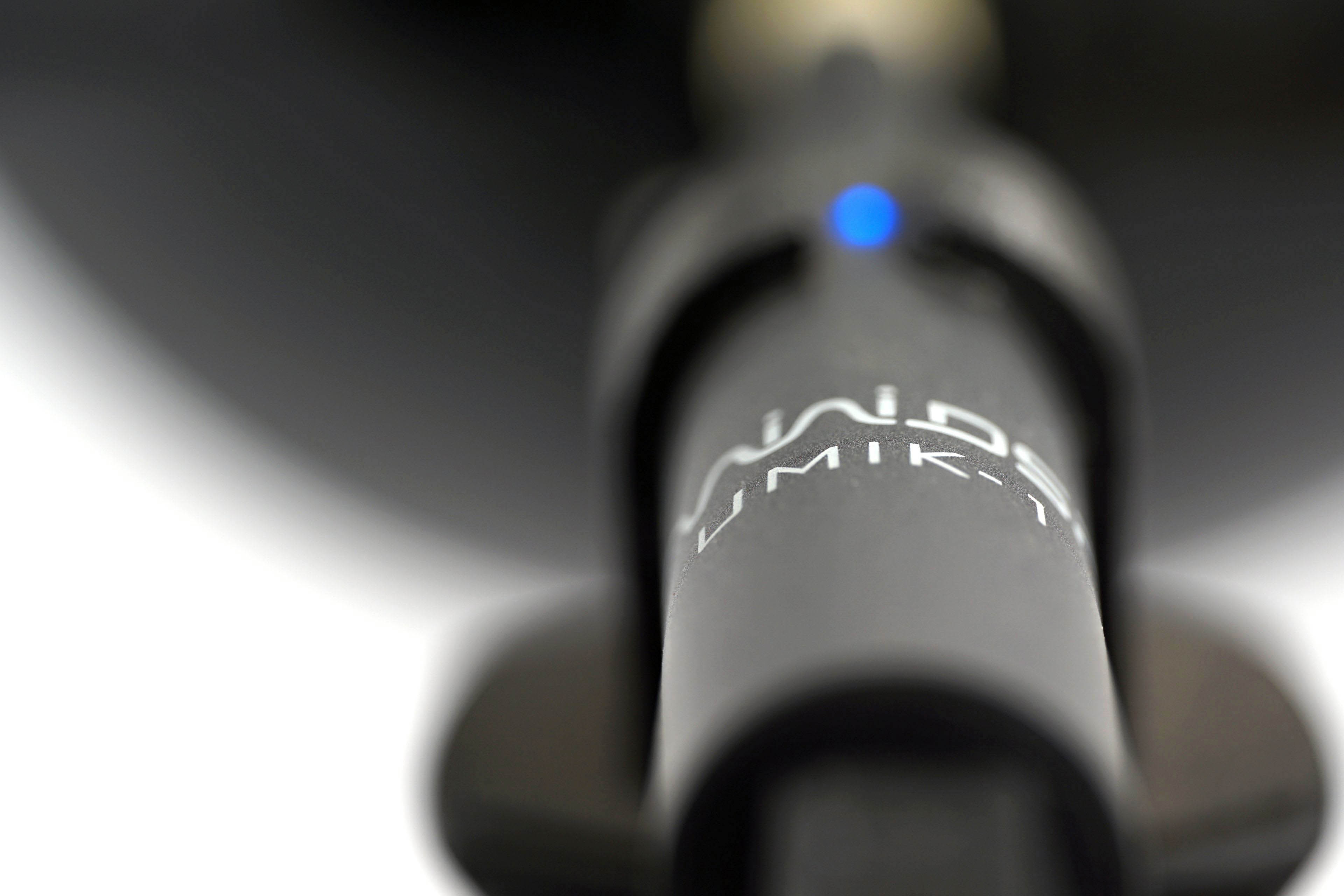
We already do this in graphics card tests, and we’ll do it for fans too, where it makes even more sense. Using the UMIK-1 miniDSP microphone and TrueRTA’s mode-specific, fixed dBA application, we also measure which frequencies contribute more and which contribute less to the sound. The monitored frequency range is 20-20,000 Hz, which we’ll work with at a fine resolution of 1/24 octave. In it, noise levels from 20 Hz to 20 000 Hz are captured at up to 240 frequencies.
The information captured in the spectrograph is a bit more than we will need for clear fan comparisons. While you’ll always find a complete spectrograph in the tests, we’ll only work with the dominant frequencies (and their noise intensities) in the low, mid, and high bands in the comparison tables and charts. The low frequency band is represented by 20–200 Hz, the medium by 201–2000 Hz and the high by 2001–20 000 Hz. From each of these three bands, we select the dominant frequency, i.e. the loudest one, which contributes most to the composition of the sound.
To the dominant frequency we also give the intensity of its noise. However, in this case it is in a different decibel scale than those you are used to from noise meter measurements. Instead of dBA, we have dBu. This is a finer scale, which is additionally expressed negatively. Be careful of this when studying the results – a noise intensity of -70 dBu is higher than -75 dBu. We discussed this in more detail in the article Get familiar with measuring the frequency response of sound.
Strict acoustic safeguards are required to ensure that these measurements can be carried out with satisfactory repeatability at all. We use acoustic panels to measure the same values at all frequencies across repeated measurements. These ensure that the sound is always reflected equally to the microphone regardless of the distribution of other objects we have in the testlab. The baseline noise level before each measurement is also naturally the same. The room in which we measure is soundproofed.
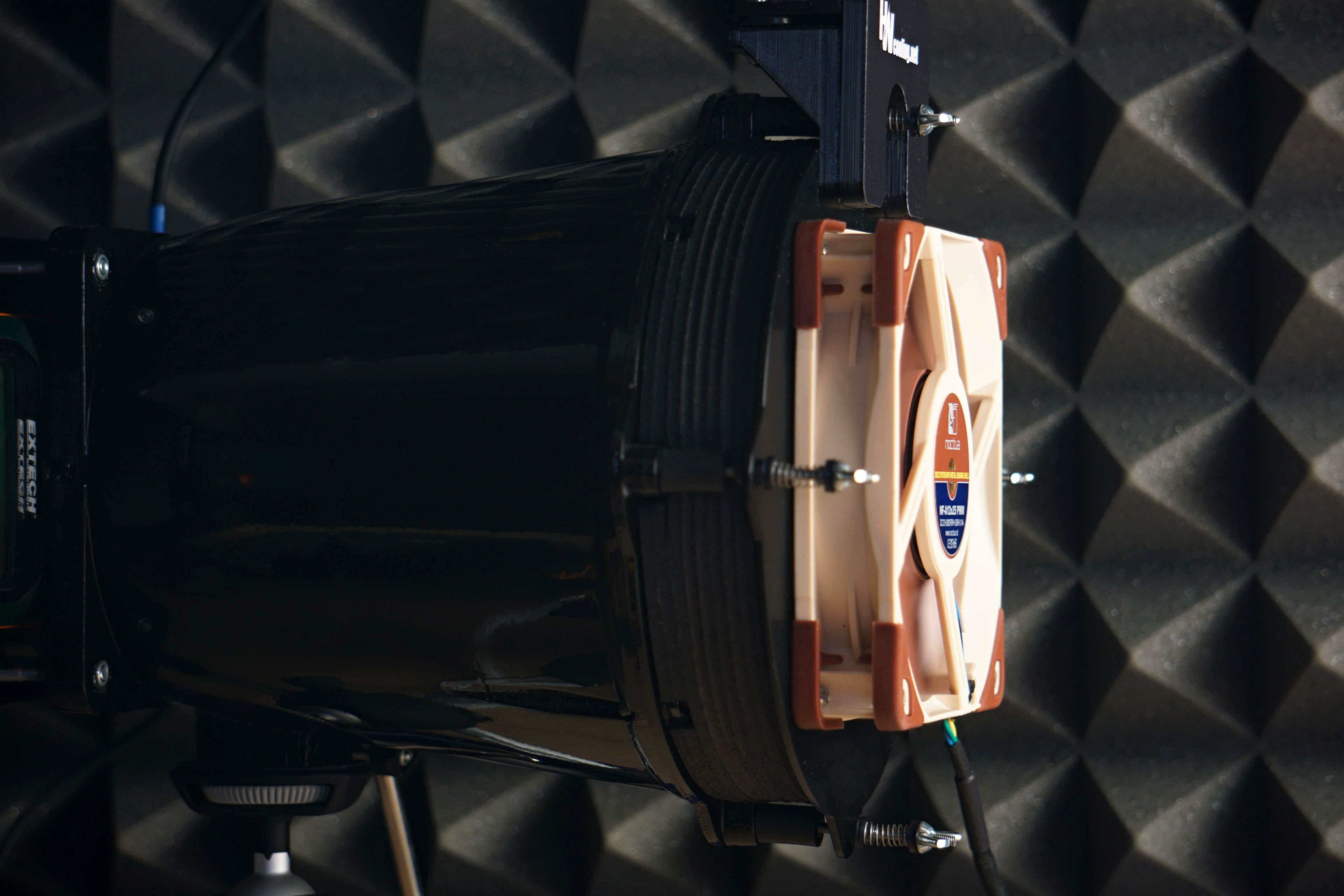
Like the noise meter, the microphone has a parabolic collar to increase resolution. The latter is specially in this case not only to amplify but also to filter out the noises that occur whether we want them or not behind the microphone. We are talking about the physical activity of the user (tester). Without this addition, human breathing, for example, would also be picked up by the spectrograph. However, this is successfully reflected off the microphone sensor by the back (convex) side of the collar. As a result, the spectrogram only contains information about the sound emitted by the fan itself.


I wish it’s possible, somehow, to test whether opposing rotation directions actually brings a benefit. It is strange there are no one that I know (out of Scythe) uses opposing rotation directions in air coolers. There are GPUs using a similar setup but I am not sure if it actually works as as stated either.
It should be possible to test this on GPUs, since on some models the fans are identical except mirrored, and invidual fan parts are obtainable as repair parts. However, they are in parallel instead of in series so the situation is different.
On graphics card coolers it’s a slightly different situation, but the same direction of rotation should be the more powerful but noisier one – the blades lead the air against each other. And this is what most manufacturers of three-fan coolers try to avoid by making the middle fan rotate in the opposite direction of the other two, outermost ones.
We will try to test it in some way in a connection in series, although I don’t know how to make it so that the only variable is the direction of rotation. For that there would have to be a counterclockwise-rotating Kaze Flex II 120. This way we can test a standard configuration on the Fuma 3 and then one where the front Kaze Flex II 120 Slim is swapped for the Kaze Flex II 120. But it won’t be quite the same, as the Kaze Flex II 120 Slim is in many ways a different fan. On the other hand, if the initial fan configuration on the Fuma 3 achieves a higher cooling performance than after replacing the front fan with the Kaze Flex II 120, the effect of reverse rotation would be demonstrable. Anyway, it would still require two models with different direction of rotation, which otherwise have the same performance characteristics.
Maybe the Thermalright TL-C12C and TL-C12, which probably also use the same motor and bearings, could be close to this after alignment to equal speed. The only thing that might be a bit distorting is the material used to make the rotor with a slightly different stiffness. Any other ideas? 🙂
Good find. The Thermalright TL-C12/C12B (http://www.thermalright.com/product/tl-c12/, http://www.thermalright.com/tw/product/tl-c12-b/) and C12C (http://www.thermalright.com/product/tl-c12c/) seem to be identical except for rotation direction. I am sure someone like ThermalLeft would be more familiar with the fan models to know if there are any other differences (or if there are other fans being mirrors of each other).
Perhaps tests can be run by using a combination of these fans (and probably some other fans as well) on several different coolers, including a fan-swapped Fuma of course. The only variable that should be changing is the Thermalright fans. Though obviously you would need to validate that they are, indeed, identical except for the rotation direction first (though it would also make an interesting review if they perform differently). Why so many fans spin counterclockwise instead of the opposite is an interesting topic by itself.
I honestly don’t know why most fans are counterclockwise-rotating. I’ll try to look for it in circles of people who might know something about it. I have some ideas, but I don’t want to speculate.
Sure, thanks. TL-C12-B will probably be closer to TL-C12C than TL-C12. Perhaps an identical material could be used as well, as far as the elements used are concerned. The TL-C12 has a different colour, so at least to some extent it will be something a bit different, with possibly different blade stiffness.
Of course, the effect of combining fans with opposite rotation directions in dual-tower heatsink will have to be analysed across multiple heatsink. Scythe did not claim to have increased the cooling performance/noise ratio of the Fuma coolers in this way (but only the cooling performance…), but if with one heatsink there would be a faster growth of cooling performance than noise, i.e. a higher “efficiency” of the whole solution would be achieved, it does not mean that this will always be the case, of course. What we discussed last time in the article on psychoacoustic optimizations applies.
Different fin profiles may react differently to the same airflow, also acoustically. I believe that most other heatsinks that have been developed with the use of fans with the same rotation in mind will be characterized by more unpleasant tonal peaks than is the case with the Fuma 3. And it also cannot be ruled out that the average to below-average Kaze Flex II does a better job on the Fuma 3 (in terms of maximum cooling performance at equal noise levels) than it would appear from tests of the fan itself. It’s all about how, with the cooler as a whole, the developers have managed to eliminate tonal peaks across the frequency band.
I’m a complete novice here, but wouldn’t the Thermaltake SWAFAN with it’s swappable blades do what you want for testing alternating fans rotation?
Unfortunately, based on the official specs, the two rotors perform differently, with different airflow, static pressure and sound levels. This suggests that the blades are different, not just mirrored copies of each other. Even if the blades were perfectly mirrored, the stator is not symmetrical, which will lead to different characteristics of the overall fan.
Note the position of the leading edges of the Thermaltake SWAFAN rotor blades. Across variants they are not on the same side, while with the Thermalright TL-C12C-B/TL-C12C they are. This means that the TR fans move the air axially in the same direction (and only rotate the air streams in a different direction), while the Thermaltake fans move the air in the opposite direction.
It’s not Kaze Flex II, but I learned the important thing from testing other clockwise fans with a wind tunnel about 2 years ago. When I tested TL-C12 and TL-C12C without any airflow correction, I got the result which claims that TL-C12C has ~10% higher noise-normalized airflow than TL-C12. Of course, I realized something is wrong. TL-C12 and TL-C12C use the same impeller geometry, motor(4 pole motor, rifle bearing), and material(PBT), so the efficiency results of each fan should be similar.
When I re-tested them after adding a flow straightener between a fan and an anenometer, their result became approximately same. The cause of the first error was the direction of rotation. For my wind tunnel without a straightener, clockwise fans can take an unfair advantage that counterclockwise fans cannot have. This may come from rotation of turbulence inside a tunnel and the vane shape of my anenometer. Since that trials and errors, I have measured airflow with flow straightener despite the fact that it acts as strong obstacle against airflow.
Maybe your wind tunnel has no problem like my one? Your wind tunnel measures a ‘pulled’ airflow by a fan and the vane of the anenometer is flat, so may I assume that Kaze Flex II’s airflow result doesn’t have any distortion?
Plus, I didn’t know about Scythe’s Grand Tornado. I think it’s one of the best names for PC fans after Gentle Typhoon. 😀
Dealing with turbulence in a wind tunnel to achieve objective results is a rather complex topic in itself. It wasn’t that long ago that we were tinkering with all possible designs, including very long tunnels, and finally ended up with what we are using. Yes, we do test fans pulling air through the anemometer for a number of reasons. One of them is the one you have already hinted at – to significantly suppress turbulence in the anemometer passage, regardless of which fan is used. Of course, a symmetrical anemometer with flat blades is also needed for this.
The topic of “correct” anemometer placement in the tunnel is a bit of a skeleton in a closet. It’s not just about the position itself, but also the things around it that have to be in perfect harmony with a given placement. It’s impossible to write a few words on this, maybe one day I’ll publish a thick book on it, we have a plethora of data on it (from the early phases when the test methodology was going through various prototypes), all well documented. And the time will come when I will start to process it for the public. But for now it is still early, in my opinion very few people would be able to absorb it. We still have some way to go before it makes sense to go deeply into even such basic topics as the fact that push/pull result ratios in airflow measurements do not correlate with results where the temperature difference (push/pull) is observed in the context of a “cooling performance” analysis.
During the development of our methodology for testing fans, I have not come across many advantages that would play in favor of an anemometer in a “pushed” configuration. I know I don’t need to explain this to you, but I will just point out to everyone else that the position of the anemometer has nothing to do with the push/pull orientation of the fan with respect to an obstacle. But back to why the “pulled” tests proved to be a better option when it comes to comparing fans of all designs as accurately as possible. We have already discussed the first reason, significantly lower turbulence inside the tunnel and the smoothing of the air streams can be achieved on a significantly shorter path than in the “pushed” case. And there is no need for a straightener, which contributes a bit to the increase in tunnel resistance, which can distort the airflow results of fans with lower static pressure. Another thing is that when pushing the air streams into the tunnel, acoustic distortion also occurs to some extent depending on the shape of the specific trajectory – the air streams hitting the tunnel walls creates a different sound in the “conical” NF-S12A than in the “cylindrical” NF-A12x25 fan. This is then, of course, to a certain extent reflected in the setting of the individual modes in the framework of normalization to the specified noise levels.
Now I have taken this very, very superficially, and we will come back to the second and third paragraphs sooner or later, and in great detail, with the support of a great deal of measured data. It probably won’t be in a week, a month and maybe not even a year, but it will come out one day. It just has to make sense, it has to be useful for more than just a handful of people who will know what it’s about. 🙂
PS: Personally, I see technical issues with the ACMA 210 as well, but I won’t comment on them definitively until we get to the LongWin LW-9266. Of course I respect that instrument as a standardized device, but there is always that question “do its data come closest to the maximally fair comparisons?”
My further enhancement for a wind tunnel should reflect your opinion. I’m still using the current tunnel because of the financial problem, But I’ll finally change it into a design that measures a pulled airflow.
The deviation between Min and Max airflow is 3~5% now(the higher airflow, the higher deviation). By using pull position, maybe I can suppress a airflow deviation at slightly low or same level even without a flow straightener because as you said, pulled airflow will be less turbulent than pushed airflow.
Meanwhile, I already knew about the acoustic distortion that comes from the a tunnel. In the past, I processed noise-normalization for fan with it installed on wind tunnel. It was a similar methodology with yours, but the problem is that I did not consider the acoustic effect of my tunnel when I had designed it. After I finished the airflow test, I got the noise – airflow result that says the order of PH-F120MP V2 > NF-A12X25 > PH-F120T30 for radiator push environment. This was obviously wrong. The cause of my fatal error was my ignorance about the noise distortion. So, I have been doing noise-normalizations with a PC case from then to resolve the problem. After I started to use PC case for noise-normalization, results of those fans became similar with other tester’s data. (NF-A12X25 ≥ PH-F120T30 > PH-F120MP V2)
Maybe I’ll stay at the method with PC case, because I’m really not an expertise about airflow – wind tunnel – noise interactions. Although there is a matter that there is a slight difference (within 100RPM at same PWM) between rotational speed measured at case and that measured at wind tunnel, it is difficult to modify the current design now. I need further research by myself before designing a tunnel that can minimize acoustic effect.
I’m looking forward to a lot of data that will be released someday. It will really help to offer detailed explanation about measurements for fans.
Of course, a wind tunnel always increases the noise level, it cannot be completely avoided. But as long as a) it is not a measurement confronting the specifications and b) the increase in noise is “fair” for each fan, everything is fine in my opinion. But to the main point:
1.) As we have already discussed above, when air streams are circulated by the tunnel, it can have quite a significant effect on the noise level of the whole system, if we consider the fan + tunnel as a system. When comparing the situations of pushed airflow, pulled airflow in relation to the tunnel and then free space flow (preferably with the fan attached to rubber bands, far and wide without obstruction), the lowest noise will of course be achieved in this third case, then usually with pulled airflow and finally with pushed airflow. Of course, it also depends on the design of the tunnel itself and the larger the cross section, the smaller the difference between pushed and pulled airflow will eventually be. The problem, and this is not objective, is that with pushed airflow the increase in noise (compared to free space measurement) can be different for each fan, which I consider to be quite unfair and distorting. The more conical the trajectory, the greater the increase in noise at the same airflow can possibly be the case when air is pushed into the tunnel. In a free space or other situation, such a fan can be quieter. Pulled airflow eliminates this quite well, because the air stream is forced into the free space, where among other things the tunnel has less resistance with respect to the fan, which in turn is useful for other reasons.
Naturally, even in a pulled airflow situation, where the air flowing through the tunnel is less turbulent, there is always an increase in noise, but from our observations the increase is always about the same regardless of which fan is on there. Nevertheless, in some cases, due to the design of the tunnel, some fans may produce resonant frequencies and tonal peaks which should be dealt with, as they naturally present a significant distortion when tuning to equal noise levels. But this is beyond the scope of the comments below an article. We will certainly, when the time comes, discuss these findings in an article.
2.) Tunnel noise is naturally a problem if the aim is to verify the noise parameters given by the manufacturer. But this is only one of the elements and it does not bother us very much when comparing fans as accurately as possible. Frankly, I have never had the ambition to measure noise according to standards and norms. Apart from the fact that it requires extremely expensive equipment, in the end I still wouldn’t get to the data that I consider to be important for practice. Measuring noise from a distance of one metre, even in a perfect anechoic chamber, means that the small details that make the difference between a very good and a great fan are lost from the sound. Of course, everyone can see this differently, it depends on who wants to achieve what with their measurements. It is true that with different noise measurement procedures, the possibilities for reproduction of the measurements decrease and sometimes it is harder to find the “common ground”. Recently, we have discussed the Magflow fan with Seasonic because it has quite pronounced tonal peaks at higher frequencies, and naturally, when someone records the sound of the same fans from a distance x times greater, the spectrograms look a bit different (and the peaks suddenly don’t look so scary anymore).
There was one more thing that came to my mind with regulating the fan to equal noise levels externally. Namely, that the thing with which the fan is in contact (for example a case) is also to some extent a source of sound depending on the vibrations on the frame. The proportion of “amplification” by the noise of the structure that holds the fan can also be different and elimination of these phenomena is extremely difficult. We have solved this by using a holder made of a material that does not get into significant resonance frequencies with the typical fan vibrations, and to ensure that the tunnel never resonates, soft mounting using silent blocks with lower hardness was necessary. In short, we have done everything to avoid this external measurement, which also increases the time effort by requiring more assembly work (at the place of normalization and then at the place of other measurements) or work around the data transfer from place to place. With CPU coolers I used to noise-normalize them in a different chamber than the tunnel in which the cooling properties were subsequently measured.
So much from my point of view on the basic things about noise measurement. It’s a very complex topic that can be discussed endlessly (and also in regard to the “appropriate” position between the sensors of the noise meter/microphone and the fan itself), but that’s why we enjoy it and I’d like to conclude by reiterating one thing. In the end, the most important thing for the people we are doing it for is always whether we come to comparable conclusions across methodologies. The slightly different details of the measurements do not matter so much, that is often nitpicking. Your fan tests and tests from QM오즈 are the only ones that interest me personally. I’ll look into the Hardware Busters results as well, but more than for practical reasons for the use of ACMA 210. So I keep my fingers crossed for your further work, you are doing a really good job! When one finds out over time that one has not evaluated something optimally and puts on sackcloth and ashes (in your case in excessive amounts), it is always very respectable. So few people have such a strong self-reflection, hats off to you.
Thank you for the substantial insight again!
Regarding the noise from a tunnel, I understand the brief principle of an acoustic interaction between tunnel and fan: Although even a tunnel with pulled airflow measurement always increases entire noise level, it makes approximately equal acoustic impact for each fan when fans make same airflow, by eliminating contribution of a wind stream trajectory which is pushed by a fan.
I’ll try to check this mechanism with my wind tunnel after finishing the current projects. Measuring the aumentation of a noise level at a same rotational speed might be enough to check it simply.
Meanwhile, I agree about the convenience of measuring noise with a fan mounted in a tunnel. It is really time-cosuming work to noise-normalize a fan, depart it from a noise bench, install it at a tunnel and seal some gaps. There are so many procedures. Nevertheless, I think it’s a problem that can be solved if I’m more diligent.
Operating fan at any structure makes a difference at noise, as you said. I think that if this problem cannot be resolved completely, measuring a noise level at PC case can be a good second workaround for me. PC fans are usually mounted at PC case as their purpose so that this method with a case may be reasonable.
On the other hand, the effort to reduce a noise amplification by vibration not only enhances the fairness of test, but will also help users at a practical aspect. (for example, applying QM오즈’s spring method to real cases?)
Maybe I’m continuing to look back and criticize my methodology because I always eager to make my work better than yesterday. Is it too many amounts of ashes? 😀 If I made no development.. I would stay at a low level:
https://img2.quasarzone.com/editor/2022/01/19/bb863e391cf36c3844ab7ba69c26c078.jpg
Anyway, thank you for the compliment and the advice that motivates me and inspires another comparison method.
I appreciate you for taking the time to reply in detail.
I’m really glad that we can discuss here together like this. Your testing of fan noise in cases has taught me one thing. Namely, that even a small sheet metal in front of the rotor is enough to achieve high tonal peaks. For a long time, I’ve associated this with a lot of edges on a large surface area and yet it’s something a little different. 🙂
“Operating fan at any structure makes a difference at noise” … and here it depends on what vibrations a fan transfers to the frame. I am afraid that their influence could distort the assumption “Although even a tunnel with pulled airflow measurement always increases overall noise level, it makes approximately equal acoustic impact for each fan when fans make the same airflow, by eliminating contribution of a wind stream trajectory which is pushed by a fan.” Of course, it also depends on the design of the tunnel and whether the tunnel can eliminate the resonant frequencies, that will contribute to the secondary noise, across the entire vibration spectrum of all the fans tested. We have been working for some time to ensure that even the fans with the highest vibrations do not transmit any vibrations to the tunnel and thus do not increase the overall noise level of the measurement system. This is what slowed down the development of the whole methodology and it was quite difficult to achieve the desired result. Especially when we had more requirements for the mounting system (also around vibration measurements and so on). Soft mounting, but at the same time tight fit will be beneficial in this respect. The higher the speed, the higher the vibrations, the higher the share of noise the tunnel itself can eventually have. Especially if it is composed of relatively light materials.
* Edit: cosuming -> consuming
While I certainly appreciate your work and expertise, these results don’t make sense.
How is it even possible for a full-sized fan to perform worse than the slim version (of the same fan)??? Not just once or twice, but the results of this data show that the Kaze Flex II 120 Slim consistently outperforms the Kaze Flex II 120.
It seems like something is off, somewhere.
While they share the same name, they’re fundamentally very different fans. For one, you can’t simply scale the rotor to reduce thickness; things like angle of attack, blade area and thickness, are all different. One thing that’s very obvious is the different number of blades.
From the results it would seem that the Kaze Flex II is better optimized for low resistance environments, while the Slim is closer to an all-rounder.
Yes, as M already wrote, the fans and their purpose are clearly different.
The Slim has only 9 blades with with almost parallel (with the main surface) blades, so very mild “angle of attack”. Contrary, the 25mm version has 11 blades with quite aggressive angle, especially at the rotor HUB.
At the same RPM the thicker should be much noisier, it is obvious => so, at the same noise level the thicker need to spin much slower. And while the airflow scales more linearly with the RPM, the pressure not.
https://imgur.com/a/nNkmNix
Donald, thank you for sharing your point of view.
First of all, it would be useful to clarify what the very non-specific word ‘better’ means to you. I don’t see any situation of the Kaze Flex II Slim 120 in relation to the Kaze Flex II 120 that is not relatively easy to clarify. Name a specific mode and I’ll be happy to try to explain why the results of both fans are what they are. Preferably coupled with the technical reasons why something “doesn’t make sense” according to you. In any case, we have to talk about specific results in specific situations.
“Better”, as in simultaneously producing higher levels of noise-normalized airflow AND static pressure in practically every single test performed…
I mean, outside of the max speed (practically useless unless you’re deaf) results, it has “better” results on literally every noise-normalized metric in every single category I’ve looked at so far.
Generally speaking, I’d love to see fan performance in an actual PC case while running workloads in environments that resemble the use case of a typical workstation/gaming rig, but that’s just me.
No need to be pedantic; to say that what I was referring to was rather obvious, would be a tremendous understatement.
I am still not clear on what you find objectionable. What exactly does not make sense in the relationship between the results of Kaze Flex II 120 Slim and Kaze Flex II 120? Please give a specific situation, a specific mode (i.e. noise level + specific obstacle) and, above all, explain scientifically on a technical level why the presented results do not make sense as you claim.
— „Generally speaking, I’d love to see fan performance in an actual PC case while running workloads in environments that resemble the use case of a typical workstation/gaming rig, but that’s just me.“
I don’t think you realize how many external influences arise in “in vivo” fan tests. That’s why everyone who does them comes up with somewhat different results.
— „No need to be pedantic; to say that what I was referring to was rather obvious, would be a tremendous understatement.“
I consider pedantry to be a necessity in this matter. For a relevant evaluation of fans it is important to avoid as much as possible the distortions that arise at the level of the different environments in which fans can be used in practice. Recommendations from data that you would obtain in a particular situation may be misleading to others. Here it is important to realize that what is valid in one case (one of an infinite number of unique situations that can occur) may not be valid in another.
I’ll give a summary of airflow comparisons between the two:
Standard = Kaze Flex II 120
Slim – Kaze Flex II 120 Slim
No Obstacles:
Standard beats Slim by 14~24% depending on noise level, differences being smaller as noise level increases, except for 31 dBA which the Standard cannot reach
Nylon Filter:
Comparisons not available because Slim touches nylon mesh; Standard performs very poorly
Plastic Filter:
Slim beats Standard by 16~120% depending on noise level, differences being smaller as noise level increases, settling at around 20%
Hexagonal Grille:
Slim beats Standard by 6~33% depending on noise level, mostly around 12%
Thinner radiator:
Slim beats Standard by 2-19% from 31 – 39 dBA; Standard beats Slim by ~11% from 42 – 45 dBA
Thicker radiator:
Both perform very similarly, within 6% across all noise levels
With no obstacles, Standard clearly performs better than Slim.
With vents with limited openings (plastic filter/hex grille), Standard performs VERY poorly among standard thickness fans.
On radiators, Standard and Slim performs pretty similarly.
My speculation? Remember, again, that the Standard has 11 blades while the Slim has 9. This is a huge design difference, and I think you can see why 11 or more blades is extremely rare among 120 mm fan designs (it performs very poorly)… it may have better performance at the same RPM, but it’s also much noisier at the same RPM partly due to increased number of blades, reflected in the lower RPM values in the Results: Speed page. Like the Arctic F120, it is also a fan with very aggressive angle of attack, and this type of design tend to be louder at the same RPM, noise level increasing rapidly as RPM increases, and has bad noise-efficiency against obstacles.
Meanwhile, the Slim, despite looking similar when looked head on, has much lower angle of attack among other design details, which make it performs decently against obstacles despite having a slimmer profile.
–“…Like the Arctic F120, it is also a fan with very aggressive angle of attack, and this type of design tend to be louder at the same RPM, noise level increasing rapidly as RPM increases, and has bad noise-efficiency against obstacles.”
Again, you hit the nail on the head.
Arctic F version (normal or Bionix) is very good in unrestricted environment, …ie outside normal PC Case (with dust filters or mash) 😊.
The only exception where it can be of some use is in some cases without filters or in big tower with bottom intake (in space between this intake and graphic card) mounted on this in PCIe slot.
https://www.akasa.co.uk/update.php?tpl=product/product.detail.tpl&model=AK-MX304-12BK
…
STS made two videos on the topic:
https://www.youtube.com/watch?v=lfwHcHibO_4
https://www.youtube.com/watch?v=by8–xABQvE
By the way, I am looking for some statistics (correlations and regressions) in Lubo’s data.
Especially in the 120 Form factor, there is a weak but statistically significant (p < 0.05) correlation between the noise and the number of blades. The correlation is strongest in the case of hexagonal grid.
I provide some box-charts to you
I am aware of ThermalLeft’s reviews/research in this field and his OA database. I also noticed very rational comments from the other two Men in Black, namely “M” and “R”. 🙂
So, I want to ask you all, if you are interested or want to share some insight or be a co-author of a potential paper, you can write me an email to pa******@***za.sk (Orcid).
I haven’t published anything on this topic yet, but I am more interested in it than useless bankruptcy prediction models, that make me sick 😛
You forgot to write that we will link to the results of your research from HWCooling. That could be a good motivation for others you mentioned to get involved? 🙂
Thank you for your work on the detailed comparison of both fans.
When it comes to designs that differ on all key points, it is sometimes difficult to predict something. It would be different if the Slim variant (compared to the “standard” variant) was only slimmed down, but kept a comparable number and profile of blades, the same motor, etc. Especially when the test modes are normalized by noise level and not by equal speeds. These (equal speeds) would be more useful for a scientific study of the dependencies between various variables of the two fans, otherwise of course the results are with comparable noise levels more practical.