

Thermal images of the heatsink
The ideal CPU cooler should not be bigger than a matchbox, and it should handle 500 W processor without making a sound. However, this is a sci-fi and we will have to rely on conventional solutions. Although Noctua NH-D15 is in many ways unusual, it is remarkable to see how its original elements affect the effectiveness.
Thermal images of the heatsink
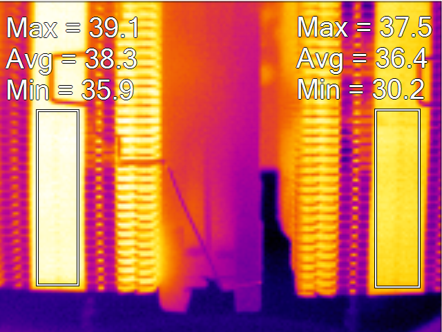
Heatmaps were created before the end of each burn test while using the same fans (NF-F12 iPPC) at different RPM and in different numbers. Measurements were done in our wind tunnel as usually. We subtracted the temperatures from the part of the heatsink that is in one axis with heatpipes. Because of the problems with the reflective nickel (even after the emissivity adjustment according to the table values, the temperature reading would not be accurate), there was a strip of black insulating tape on it.
▽ 2× NF-F12 iPPC. On the left 24 V (~ 2000 rpm) and on the right 9 V (~ 765 rpm) ▽
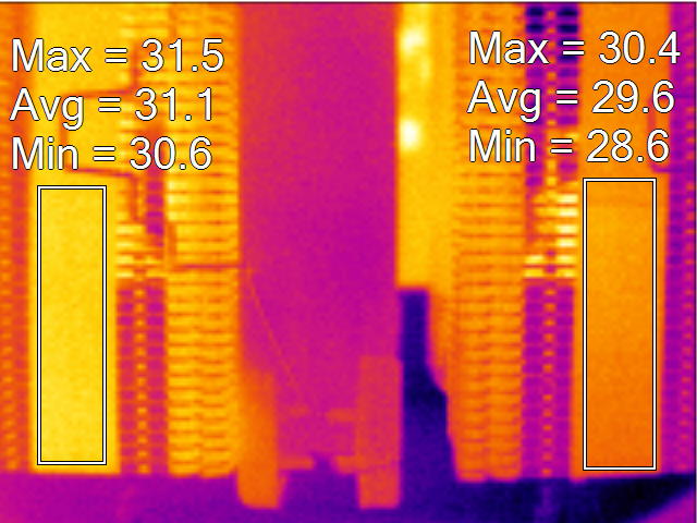
▽ 1× NF-F12 iPPC. On the left 24 V (~ 2000 rpm) and on the right 9 V (~ 765 rpm) ▽
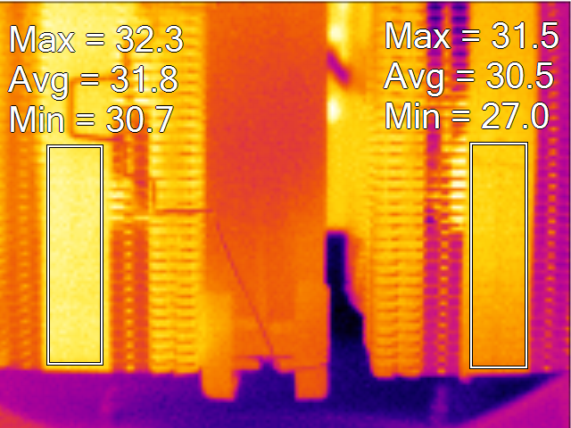
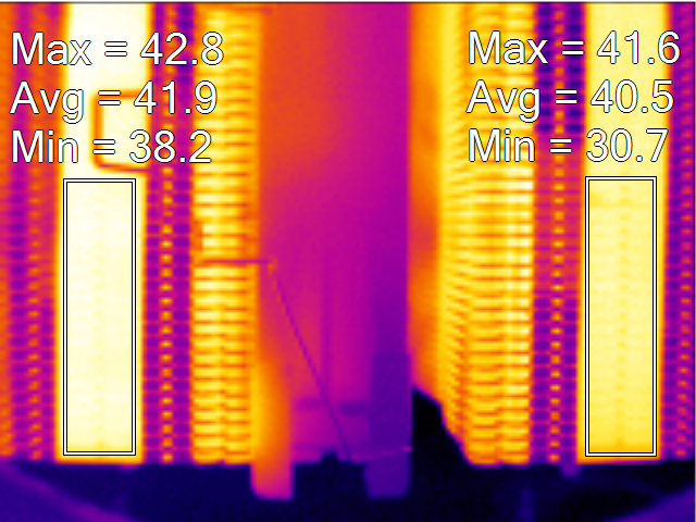
Note the increase of heat from the heatsink after removing the first fan. And especially with low RPM. At a high flow rate, the difference was smaller and the effectiveness of very intensive suction is thus seen. This also indicates a smaller contrast (and therefore higher heating) of the fan frame.
- Contents
- How we were testing
- Cooling the MOSFETs
- With the same fans
- Thermal images of the heatsink
- Passive mode (+ prints of the compound)
- Conclusion