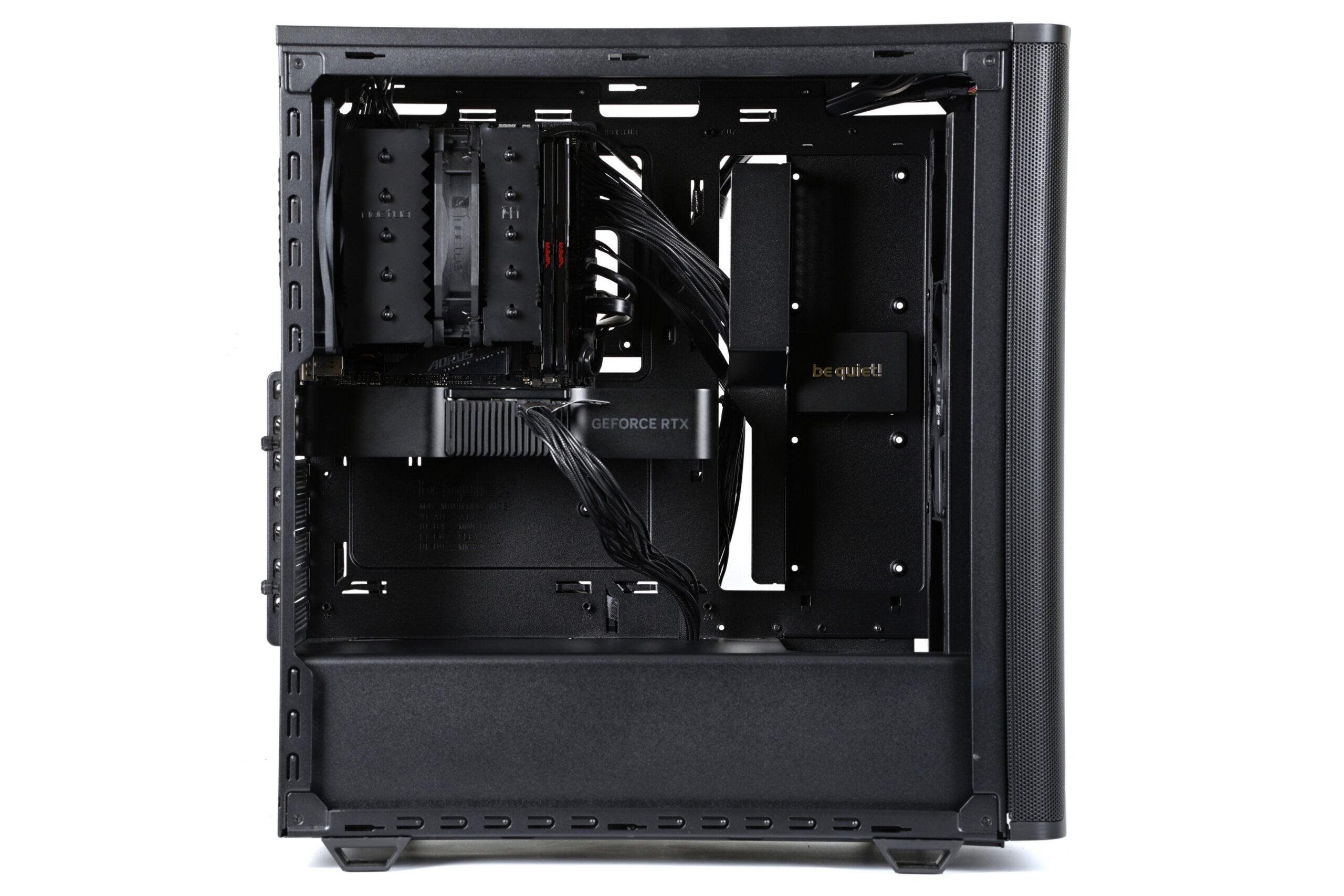
This article covers the basic details of computer cases. This means the content will include knowledge on how PC cases are categorized by size, what their components are (and why these are often used in modern designs), and also, for example, how and where individual components are installed. There is more to computer cases and what lies behind how they “function.”
Main parts from the outside…
A PC case is usually shaped like a cuboid, so it has six sides—two side panels, a top panel, a bottom, and a front and rear panel. At the rear, there is typically (unless it’s a non-traditional case layout) the input-output connectivity with connectors for the motherboard or expansion cards (e.g., graphics card) and then an exhaust fan ensuring the removal of air heated by the components inside the case. This can also be in the top section, which usually also has a position for installing a liquid cooler.
A radiator with fans in the top position, besides cooling the processor (or possibly the graphics card), also serves as fans expelling heat from the case into the surrounding environment. Above these fans, there is often a dust filter that prevents unwanted debris from entering when the computer is turned off. Dust filters are also found at the front or bottom. These are usually behind the case fans (also called system fans) to allow the least amount of dust to enter along with the air. Such filters are also found in the bottom section under the power supply. This is to prevent its components from becoming clogged with layers of dust. Naturally, this reduces their cooling efficiency.

Important external parts also include connectors (typically routed to the front, top, or side panel) with control buttons (to turn the PC on or reset it) or indicator LEDs (indicating the powered-on status of the computer or internal storage activity).

… and from the inside
The connectors and buttons on the case are connected to the motherboard using various cables. These cables are linked to their respective connectors. External connectors (i.e., those on the outer shell of the case) have various internal connectors (i.e., those through which the external connectors are connected to the motherboard).
1x Fig. (detail of cables from front panel connectors. Will be added soon)
For 5-gigabit USB 3.2 gen. 1 connectors, it’s a 19-pin connector, to which two external USB ports can be connected. For USB Type-C connectors, it’s a symmetrical connector where one such internal connector corresponds to one external USB port. Speeds can vary, even higher than 10 Gb/s, and are defined by the transmission properties of the cable between the case and the motherboard.
1x Fig. (detail of connected USB-C connector. Will be added soon)
From the front of the case, you can also pull out 9-pin connectors. With these, the pin breakout is important because it determines whether it’s a connector for USB 2.0 ports (or for a CPU cooler display) or for an audio connector. The audio connector also has four pins in one row (like the USB 2.0 interface), but the position of the individual pins is different. The connector intended for audio has, in the row with four pins, one pin also at the very edge, whereas for USB 2.0 this position is blocked and all four pins are next to each other (with a blocked corner).
1x Fig. (9-pin audio/USB connectors side by side. Will be added soon)
Positions for individual components: The case has several of these, whether for the motherboard, expansion cards, memory storage, fans, or cooler radiators. All these positions are discussed in detail along with illustrations in the next chapter of this article.