This article covers the basic details of computer cases. This means the content will include knowledge on how PC cases are categorized by size, what their components are (and why these are often used in modern designs), and also, for example, how and where individual components are installed. There is more to computer cases and what lies behind how they “function.”
Installing components…
When mounting individual components, different sequences can be applied. Sometimes it’s more convenient to install the motherboard first, other times the power supply, for example; it varies. However, it’s often true that the smaller the case, the more these aspects need to be considered. In other words, with larger cases, you usually don’t need to think too much about which component takes precedence, as they are spatially larger, which usually correlates with easier handling during the installation of computer components.
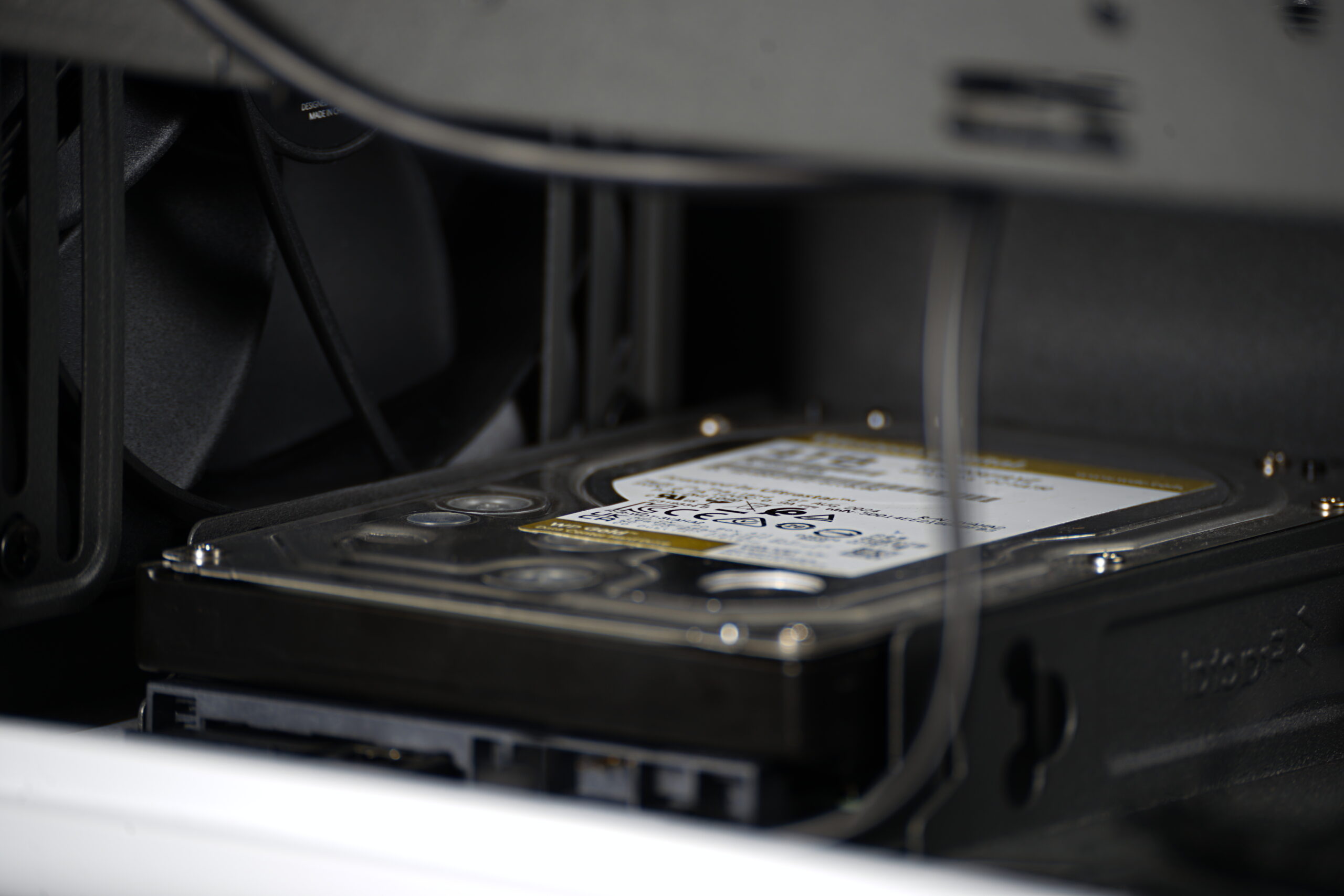
The motherboard is mounted onto standoffs, to which it is secured with screws through mounting holes. Larger motherboard formats have more of these holes (the ATX motherboard format has nine), smaller ones have fewer (the Mini-ITX format has fewer). The standoffs sometimes need to be installed additionally, because the case comes from the factory equipped with sometimes a smaller number than is optimal for the given motherboard format. However, sometimes the standoffs are pre-installed in full number, anticipating the mounting of the largest supported motherboard.


For cleaner cable management (often also associated with more efficient cooling), many modern PC cases have pass-through holes, through which cables can be routed behind the motherboard, out of reach of the front section with the coolers. The back side, besides pass-through holes for threading cables, is also equipped with cable ties or loops attached to the case’s metal structure, allowing these cables to be properly secured against unwanted movement.
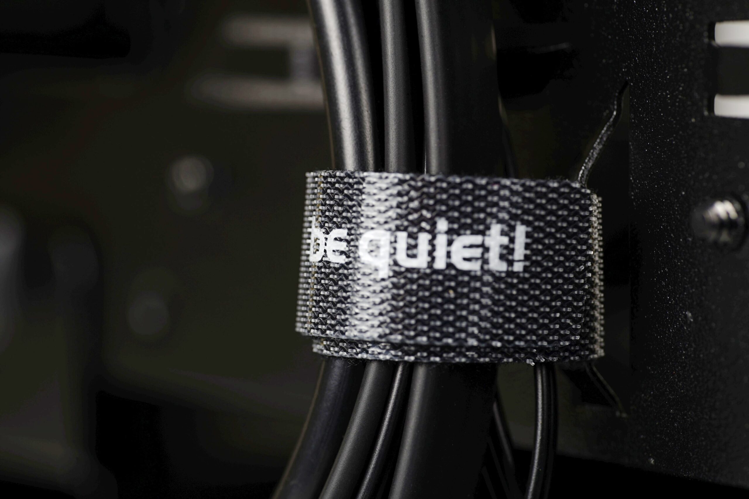
This system (with cables on the right side) is also popular for a cleaner appearance. Especially at a time when many cases have tempered glass on the left side instead of a metal side panel, allowing a view inside. This concept (“for the best possible appearance”) is pushed even further by motherboards with connectors on the back of the PCB. The position of the case’s pass-through holes then reacts to this, as is the case with Fractal Design North XL cases with the RC suffix in the designation (Fractal Design North XL RC).
… including front panel connectors and buttons
As mentioned in the previous chapter, cables from the case are also connected to the motherboard. From USB ports and from control buttons or indicator LEDs: In the case of buttons and LEDs, we speak of the “front panel” connection, so this is often indicated in the case’s accompanying materials. Sometimes you have all connectors together, other times they are separate (Power_Switch or Reset), and this also applies to LEDs (Power LED or “HDD” LED), where extra attention must be paid to polarity. This matters because an LED is a semiconductor component and it only lights up when the “+” and “-” are connected correctly. These poles are indicated both on the connectors coming from the case and on the motherboard connector.
1x Fig. (connecting front panel LEDs. Will be added soon)
Then, the CPU cooler must also be installed in the case, whether it’s a tower design with a heatsink and fan above the CPU itself or a “liquid” variant. Its radiator is installed on the case structure, and only the block attaches to the CPU. This block is connected to the radiator via tubes through which liquid circulates to carry heat away from the CPU to the radiator. In the radiator, the liquid flows through channels between the fins, and fans are used to dissipate the heat into the surroundings. These are installed on the radiator itself. But we are digressing a bit from the case here; the important thing to know is that no matter what type of cooler you use, it’s always important what size (cooler) fits into the specific case. This information is provided in the case’s technical specifications, where you should look for the size of supported radiators or the maximum height for tower coolers. These two figures are authoritative for information on which coolers can be installed in the chosen case.

Something similar applies to the graphics card and the power supply. With these components, their size is also important in terms of whether they fit into the case. For graphics cards, the maximum length is often stated, but height is also important to avoid, for example, collisions between the graphics card and the bottom of the case. This can happen with larger graphics cards. For power supplies, you might not be able to install larger physical formats (e.g., ATX) and only smaller ones (e.g., SFX) will fit. Or, even if a larger format fits, the mounting holes for a smaller PSU format might not be available. These (mounting holes) are different, defined by a different spacing. The parameters often also state the maximum length for power supplies, which can vary even for standardized formats. For example, ATX format power supplies can have different lengths, e.g., 140 mm, but also 180 mm. It varies from unit to unit.
And finally, storage—2.5″/3.5″ drives. In the form of SSDs or HDDs. These are installed either in separate cages or in various locations on the metal, for example, in spaces behind the motherboard. These positions (for 2.5″/3.5″ drives) are gradually decreasing with the growing popularity of M.2 format SSDs. These install directly into a slot on the motherboard and practically do not require case support as such.