The motherboard is a component that’s commonly not even listed in the hardware specifications provided by PC vendors or sellers, ironically. Yet it is one of the most important components, because it interconnects almost all the other parts and has to handle a lot of work. In this article, we’ll look at what you should know about desktop computer motherboards and how to handle them when building a PC or performing maintenance.
PCB
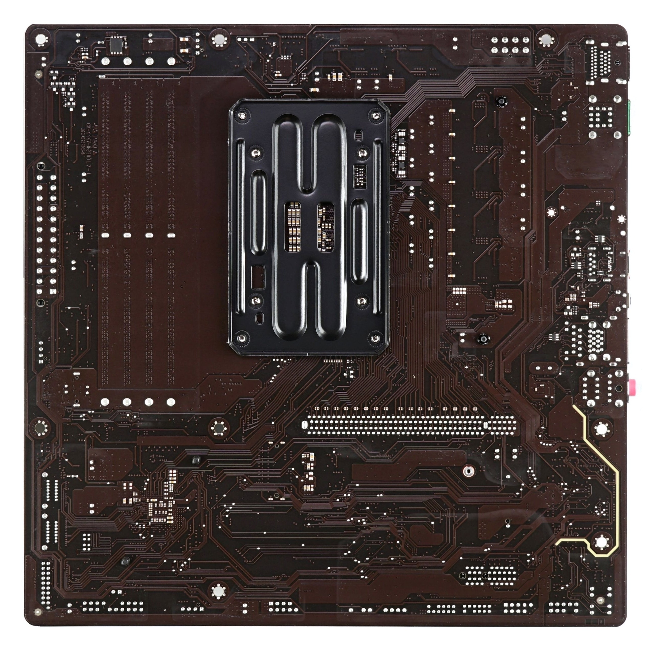
The main part is the printed circuit board (PCB) itself, which forms the motherboard, usually across its entire footprint. The PCBs used are generally multilayer. Some cheaper boards are still manufactured with a four-layer PCB, but higher-performance and better-equipped boards typically already have a PCB with more layers, which is generally considered to be of higher quality.
The quality of the printed circuit board affects not only its stiffness (resistance to flexing). Personal computers use some interfaces with very high communication frequencies—PCI Express 4.0, or 5.0 (and subsequent new generations of this interface in the future), but especially the traces carrying signals between the processor and memory modules. These high-speed interfaces are highly sensitive to interference and signal quality, placing considerable demands on the quality of both the design and manufacturing of the PCB (in addition to the quality of other components).
Slots, Connectors, and Sockets
The primary function of the PCB is to provide interconnection (both data and power) between all components on the board and between the connectors and slots to which additional hardware and components are connected. These include slots for PCI Express cards (or older ones, e.g., PCI), DIMM slots for memory modules, and M.2 slots for SSD modules.
M.2 slots have a specific physical design, but they are wired with the standard PCI Express interface signal (usually four lanes). They can be converted to a PCI Express ×4 slot using an adapter. However, M.2 slots can also provide SATA and USB connectivity (for wireless modules).
M.2 slots are differentiated by which of these connectivity types they support (Key B for wireless adapters, Key M for SSDs, and Key B & M supporting both) and also by what length of modules they support (types 2230, 2242, 2260, 2280, and less frequently the longest type 22110).

An important feature of many boards is an M.2 slot cover, which is intended to serve as a passive cooler for SSDs installed in the M.2 slot.
Types of PCI Express Slots
PCI Express slots exist in several types. The “long” PCIe ×16 type provides 16 PCI Express lanes and offers the highest bandwidth. It has a retention latch at the end (new boards often provide various mechanisms to make it easier to operate) and is primarily used for installing discrete graphics cards. These cards can have a maximum power draw of about 75 W if slot-powered. Higher power consumptions are possible, but that requires powering by cables via additional connectors on the card.
PCIe ×16 slots today often feature metal reinforcement and strengthened anchoring to the PCB. This is due to the increasing weight of high-performance graphics cards, which can damage PCIe ×16 slots. Even with reinforced slots, we recommend using a graphics card support bracket inside the PC case to prevent the card from sagging and putting pressure on the slot.
For other peripheral cards, PCIe ×4 slots were designed, which provide only four lanes instead of sixteen. These slots have no latch at the end. In servers, you may also see the longer ×8 slot with eight lanes, but PCs do not use this type.
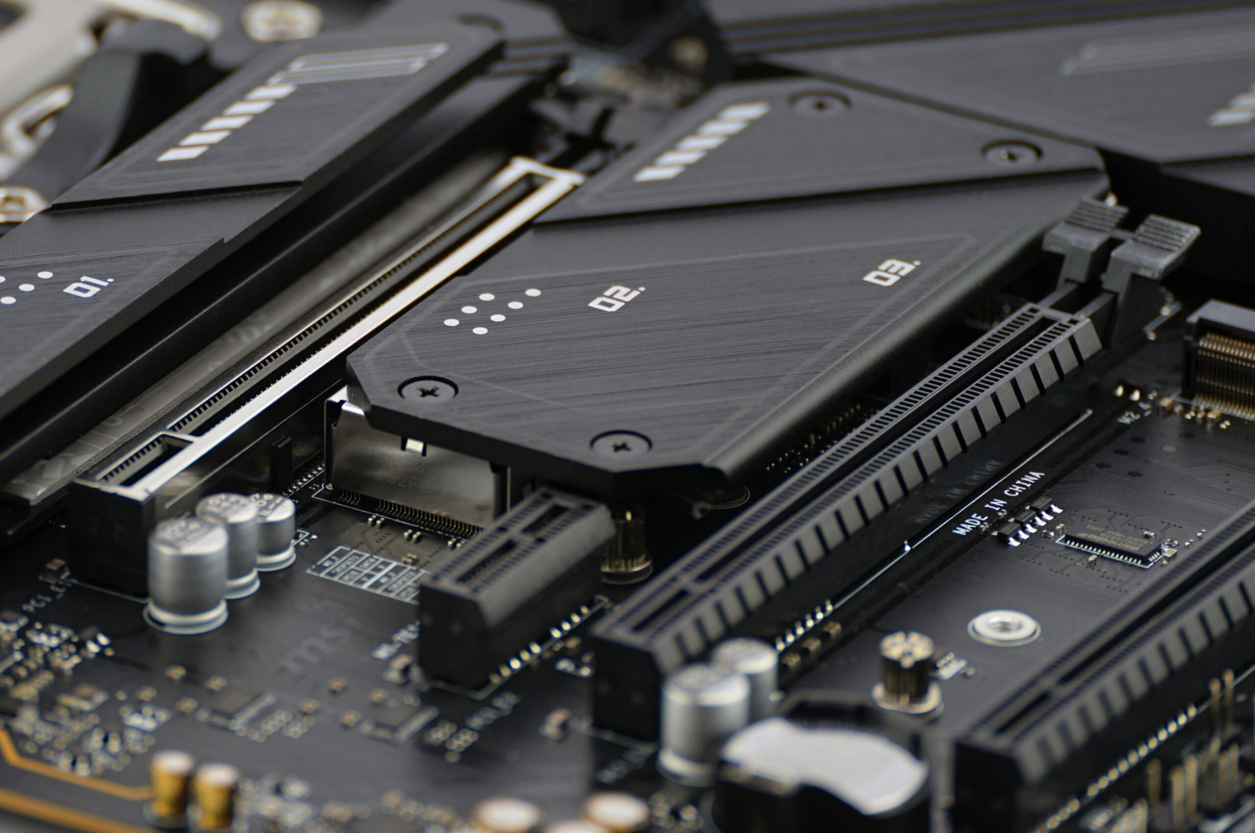
The third standard type of slot in personal computers is the PCIe ×1 slot, which provides a single data lane and is the narrowest. It also lacks a latch. PCIe ×2 slots are not commonly used. You may encounter a situation where a ×4 or ×16 slot has a longer physical design but has fewer lanes electrically connected, for example, only four or just two. PCI Express cards can use fewer lanes than they maximally support, automatically switching to a mode with a lower count.
For this purpose, open-ended (cut-out) slots are sometimes also used on boards. These allow installing, for example, a PCIe ×16 card into a ×4 or ×1 slot, with the rest of the card’s connector protruding from the end of the slot (you need to be careful that it doesn’t touch or short-circuit anything else and that the card has sufficient support—heavy graphics cards would be problematic).
Ports
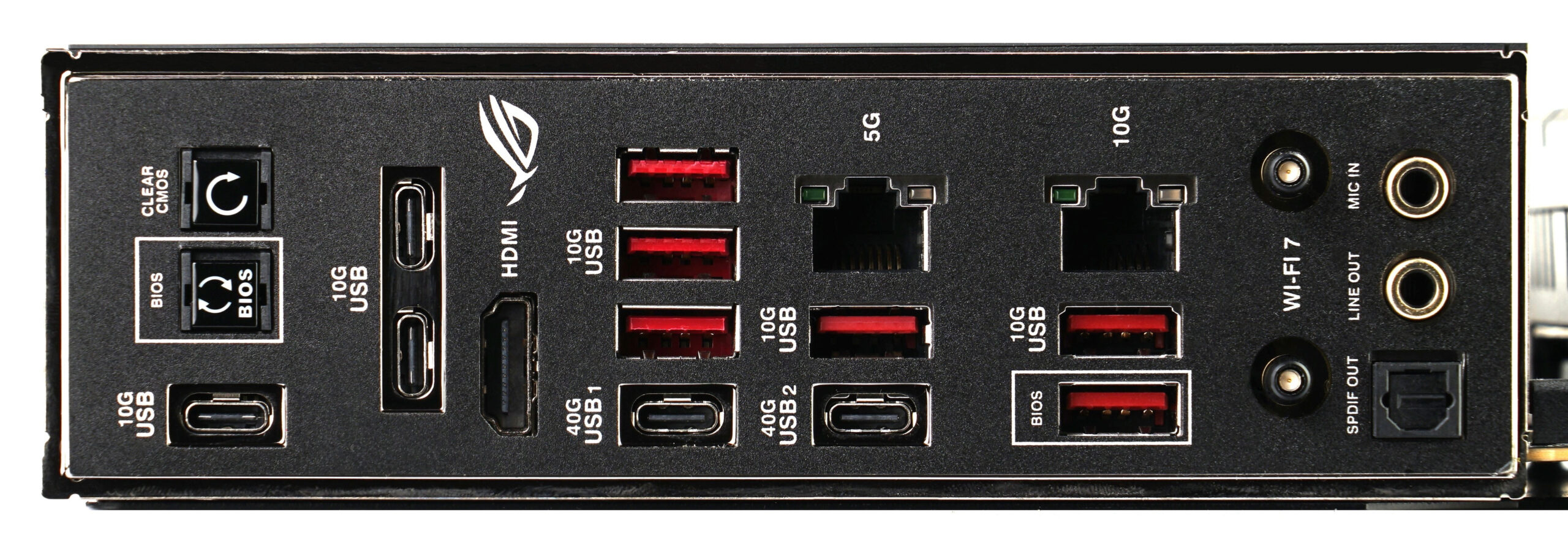
The board also provides various ports: video outputs, audio, network adapters, and USB ports on the so-called rear panel, which on ATX boards is located in a standardized and precisely defined zone that all cases account for. The arrangement of ports within this zone, however, is optional, enabled by the fact that each board is supplied with a metal plate or an “I/O shield” that fills the standardized cutout in the case, and this shield can thus be custom-fitted to the specific board’s port layout.
Additional ports can be provided by the board outside this standardized area via headers, to which cables connect, for example, ports on the front of the case, or additional ports routed to cover brackets installed in PCI Express slot positions.
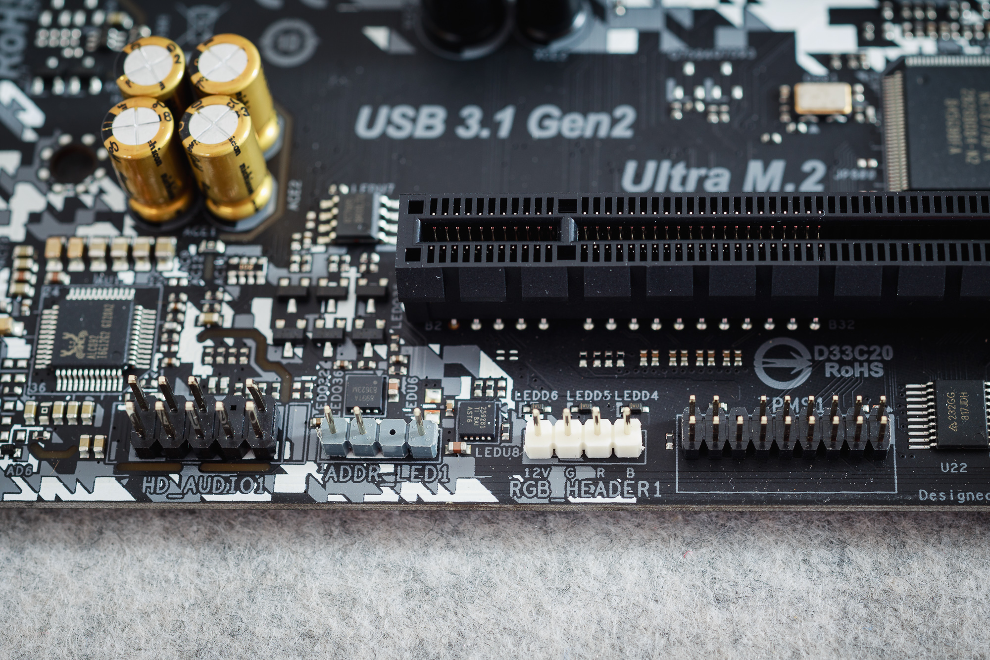
The board also provides connectors for connecting decorative RGB or ARGB lighting and, most importantly, fans. These headers not only power the fans but also allow monitoring their RPMs and controlling them via voltage level or pulse-width modulation (PWM).
Processor Socket
A special case is the processor socket, today usually located in the area above the expansion slots. The socket changes over time according to the connectivity needs and power delivery requirements that must be provided to the processor.
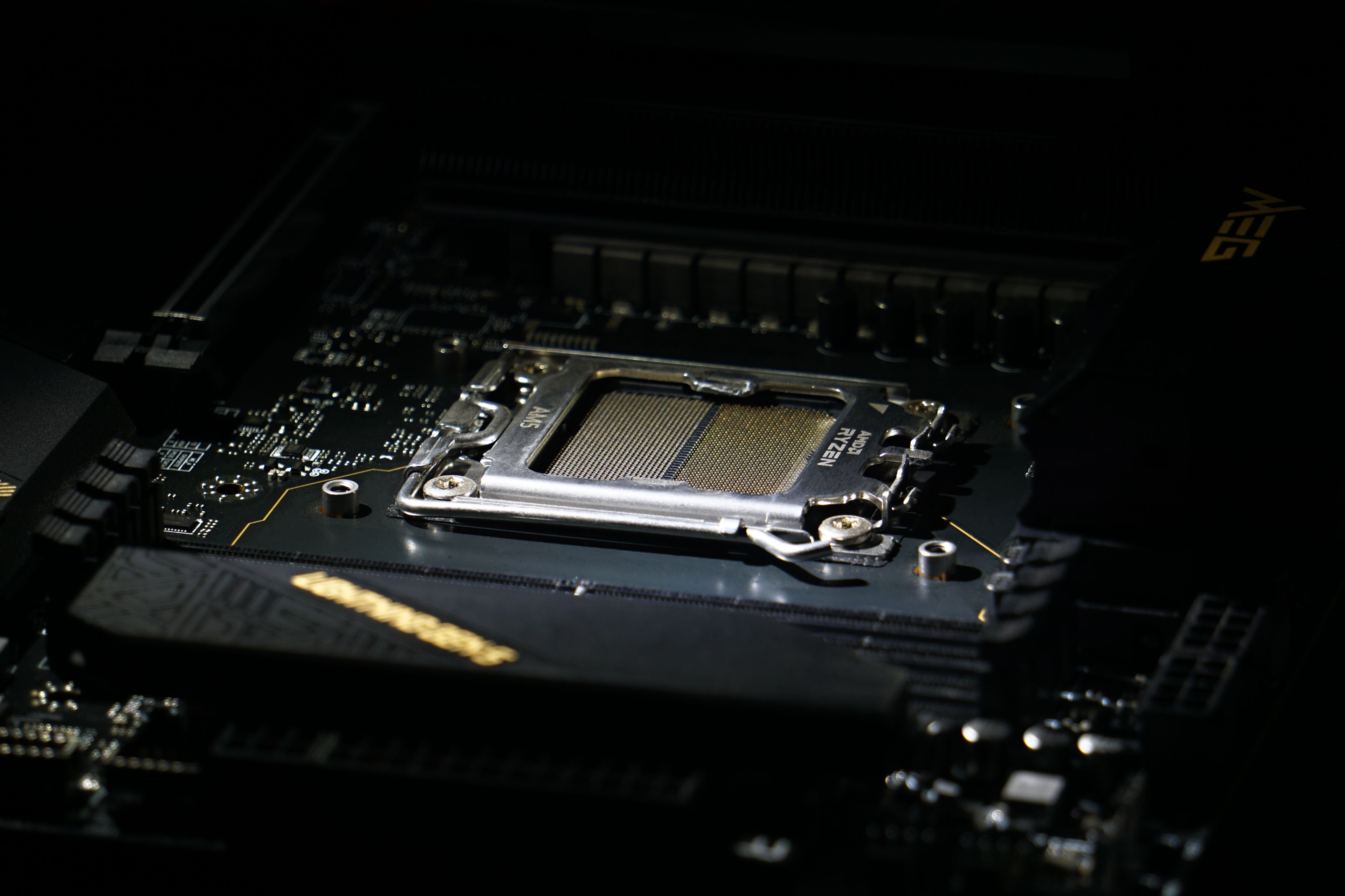
Which generation of socket (for example, AM4 and AM5 for AMD) is on the board determines which processors can be installed. The socket has mounting holes around it and, where applicable, a clamping mechanism for installing the processor cooler. This tends to be standardized for broad compatibility, but not universally—the mounting differs between processor brands (Intel and AMD) and their generations (for example, the mounting system for LGA 1700 and 1851 sockets is not compatible with mounting for previous Intel platforms).

Chips
In addition to slots and sockets, the PCB has all sorts of necessary components soldered onto it, from resistors and capacitors to various chips. These can include signal repeaters, controllers for RGB LEDs and other functions, but most importantly, the board is equipped with a chipset. The name is a bit misleading because, although it was once composed of multiple chips, today all the remaining functions are typically contained within a single chip, which is often called differently these days, such as the Platform Controller Hub (PCH).

The chipset primarily provides connectivity for USB ports and SATA for storage drives and optical drives, and several PCI Express lanes for other peripherals and slots on the board are usually also routed from it. Lanes connected to the chipset are used for devices less dependent on performance, while, for example, discrete graphics cards and NVMe SSDs are better installed in slots connected to the PCI Express controller in the processor. Information on how the slots are connected should be included in the board’s specifications or manual.
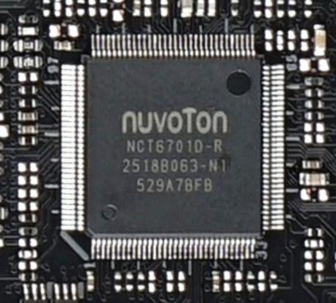
Some older “legacy” functions (SMBus, serial port, control of indicator LEDs, but also, for example, fan control) are handled by a separate chip known as the Super I/O, which is usually not considered to be a part of the chipset. The chipset is typically specific to a particular processor platform and board generation, while Super I/O chips are more universal and change at a slower pace.
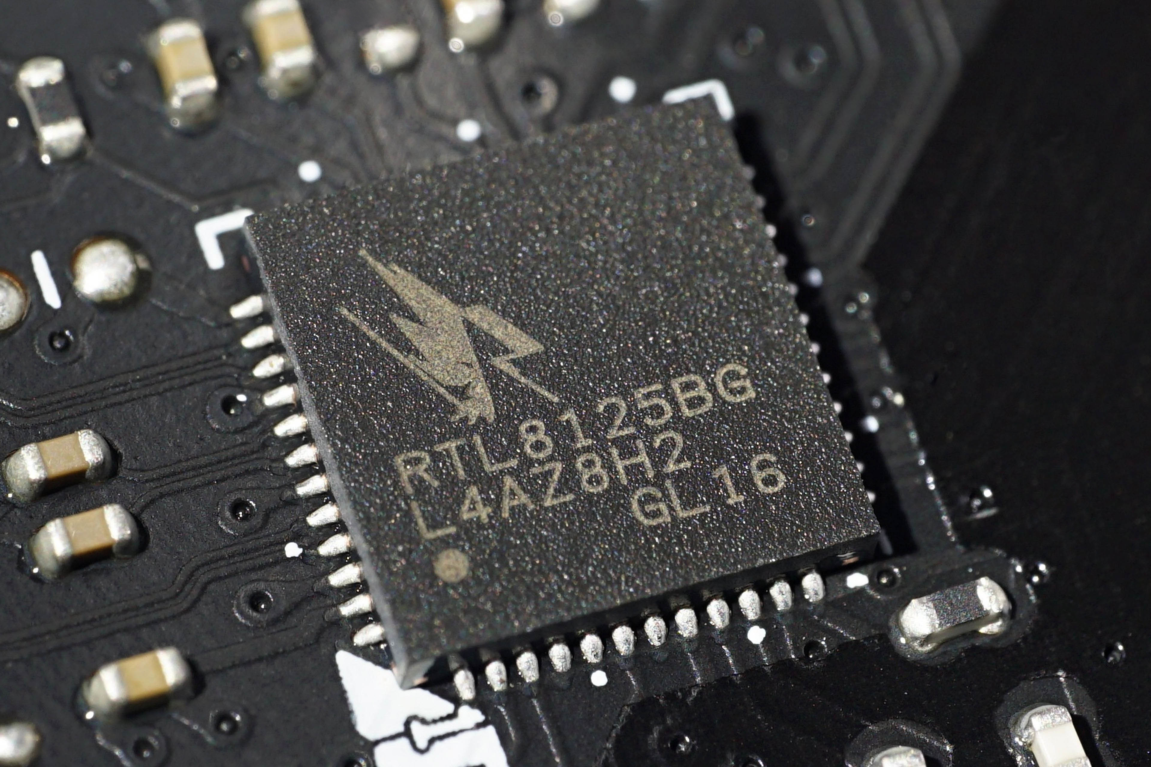
In addition to these essential components, the board may contain a number of other chips. An integrated Ethernet network adapter and an integrated audio adapter are almost always present. This was not always the case; these components historically used to be on separate cards, but since around the beginning of the century, providing an integrated solution directly on the board has become standard. Many modern boards also offer Wi-Fi and Bluetooth wireless connectivity, but this is most often installed on a replaceable M.2 module (and can thus be removed or upgraded).
BIOS
An important integrated circuit on the board is the chip (using SPI Flash non-volatile memory) that stores the motherboard firmware (UEFI, the historical term BIOS is also used). This is critical for the board’s functionality and can be updated—either via software running on the computer, or, on newer boards, also using functions usually called USB Flashback and similar. These allow flashing a firmware image to the chip from a USB flash drive by pressing a button, even without a CPU installed and without the computer needing to be able to boot. This feature is important, for example, because new processors often require a firmware update to function, but previously this required first getting the system running with an older, already supported CPU. These functions can also be used to revive a board whose firmware has been corrupted for some reason, which previously required the use of an external programmer.
The Board Menu in UEFI / BIOS
The UEFI (and previously BIOS) firmware also provides one very important capability. By pressing the designated key during computer startup, you can open its text-based or even graphical menu, where various settings for the motherboard, processor, and chipset can be configured. Motherboards also often have another keyboard shortcut to bring up a boot device selection menu for choosing the storage device or other source from which the operating system should start.
A separate chapter regarding the semiconductor components on the board is the VRM (voltage regulator module), or power delivery. This is a system of components that converts the voltage for the processor from the 12 V supplied by the power supply (via a separate PSU cable usually labeled ATX 12V2) to the low voltage (up to about 1.5 V, but with high currents) that the processor consumes. The VRM consists of capacitors, inductors, and MOSFETs or so-called Power Stages, which integrate multiple components together. A PWM controller that manages the power delivery is also located on the board.
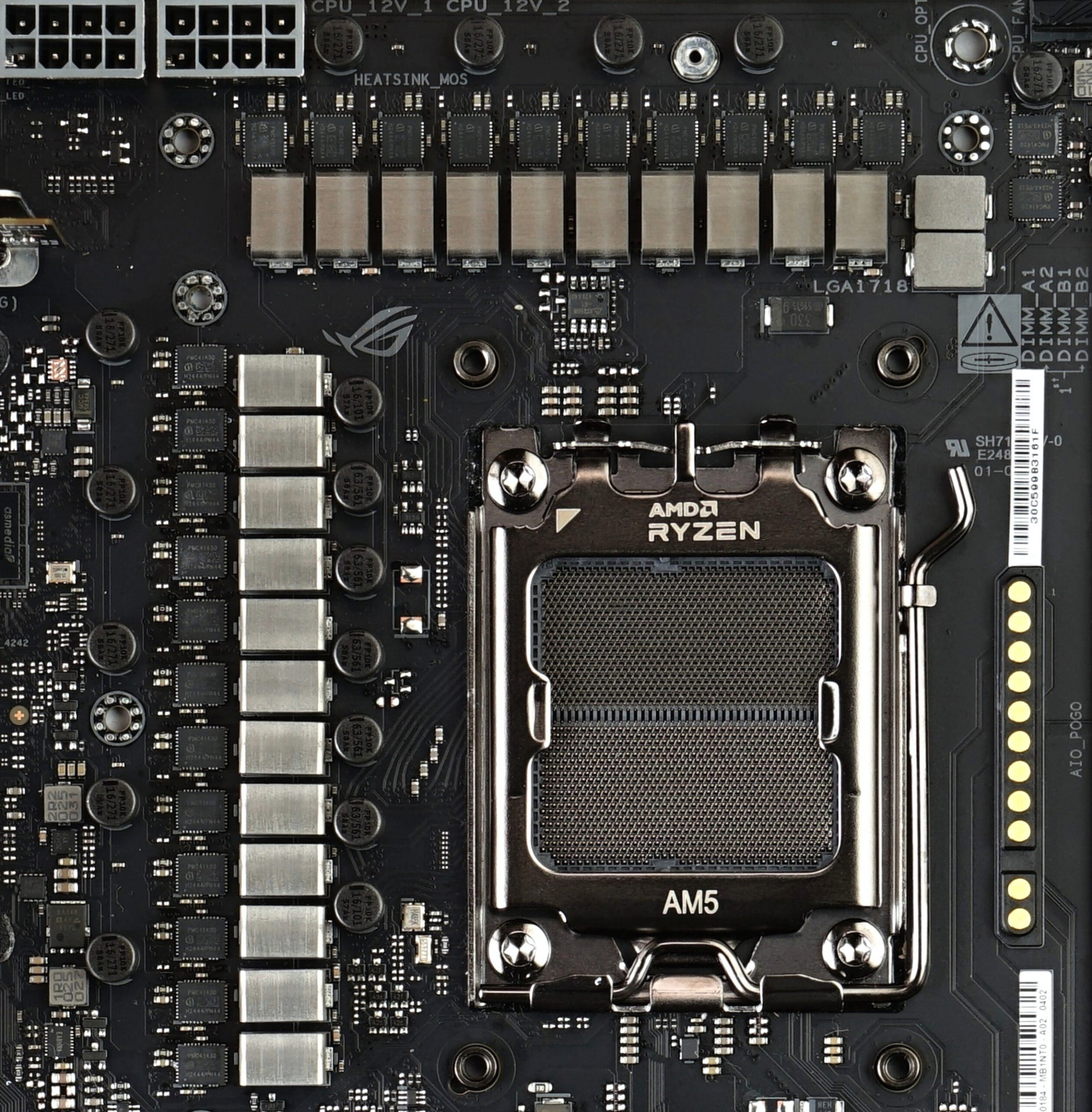
Power circuits of this type have multiple phases and multiple sections for different parts of the processor (CPU cores, SoC, integrated GPU), as well as additional ones for powering the memory. Other components like the chipset may also be powered via their own voltage regulators because the 3.3 V and 5 V voltages supplied by ATX power supplies are too high for modern electronics.
The power delivery, as well as the chipset, are usually equipped with aluminum heatsinks, sometimes even active coolers with fans. Unlike the CPU cooler, these coolers are factory-installed and are not intended to be changed by the user (although with the appropriate DIY skills, it is possible).


On today’s boards, heatsinks have also often transformed into various covers with a partially decorative function. These can cover parts or even the entire PCB on the top side. The board may also have a similar cover on the underside, which then primarily serves to reinforce it, thus having a function similar to a “backplate” on a graphics card.
Article continues on the next page…
⠀