The motherboard is a component that’s commonly not even listed in the hardware specifications provided by PC vendors or sellers, ironically. Yet it is one of the most important components, because it interconnects almost all the other parts and has to handle a lot of work. In this article, we’ll look at what you should know about desktop computer motherboards and how to handle them when building a PC or performing maintenance.
Beware of Static Electricity
Computer components are sensitive to static electricity, which can expose chips to dangerously high voltages. The correct procedure is to use an anti-static wrist strap when assembling the computer and handling components.

In a home environment, where you typically won’t have one, it is recommended to “discharge” yourself during work by touching a grounded object, which could be, for example, a metal radiator (though they are not always guaranteed to be grounded). For the same reason, it is not recommended to work in clothing that tends to generate static charge (you’ll know it by getting “shocks” while wearing it) or to place the motherboard and hardware on a carpet.
When assembling components together, including the motherboard, do not have peripherals connected into ports and do not have the computer’s power supply connected to the mains. This prevents, for example, the computer from turning on spontaneously when the CPU cooler is not yet installed, and similar issues.
Recommendations for Assembly
The ideal way to install components onto the board is to remove it entirely from the computer and place it on a flat surface before inserting memory modules and the processor. The reason is that inserting them can sometimes create considerable pressure, under which the PCB can flex. This could potentially damage the board, and it’s best to avoid it. Unfortunately, inserting power supply connectors, for example, where the same problem occurs, typically must be done after installing the board in the case. To prevent flexing, it is advisable to support the PCB from the underside with your hand (through some insulating material) while pushing the often stubborn connectors (or memory modules) from the other side.
Installing the processor while the board is standing upright in the case is strongly discouraged. This is because gravity may prevent it from being inserted evenly, or it may shift during insertion and locking. Cases are known where this led to catastrophic component destruction! Insert the CPU into the socket when the board is placed horizontally on a table outside the case, and ideally install the cooler in this position as well. If for any reason the board cannot be removed, at least lay the entire computer on its side before assembly so the board is horizontal.
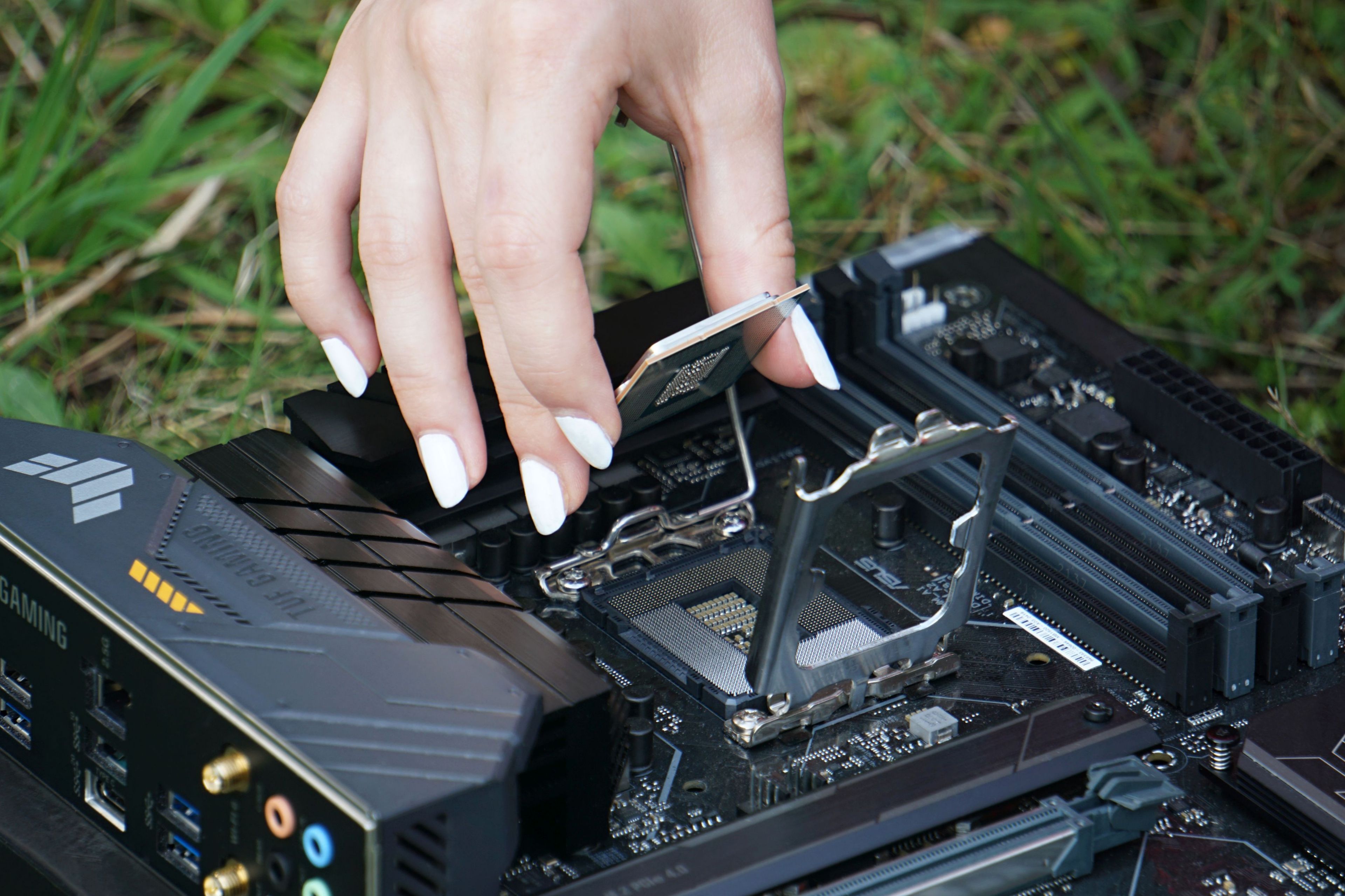
Typically, you cannot install the processor incorrectly into the socket if you proceed thoughtfully and gently. The plastic surrounding LGA sockets has cutouts or notches corresponding to the shape of the processor, which should ensure it can only be inserted in the correct orientation. With PGA sockets, some pin holes are missing, which has the same effect. Always install the processor by simply placing it, do not push on it! If it seems like it doesn’t fit in place, you are most likely making a mistake. Therefore, never resort to brute force and do not try to force components into the board, nor drive them home by screwing down the cooler onto a misaligned processor. Find out why the CPU doesn’t fit in the socket. It could be, for example, bent pins, which can be carefully fixed, but the reason could also be that you are trying to install the CPU incorrectly or have the wrong CPU. Attempts to overcome resistance very easily lead to destroying the CPU, or even the board as well.
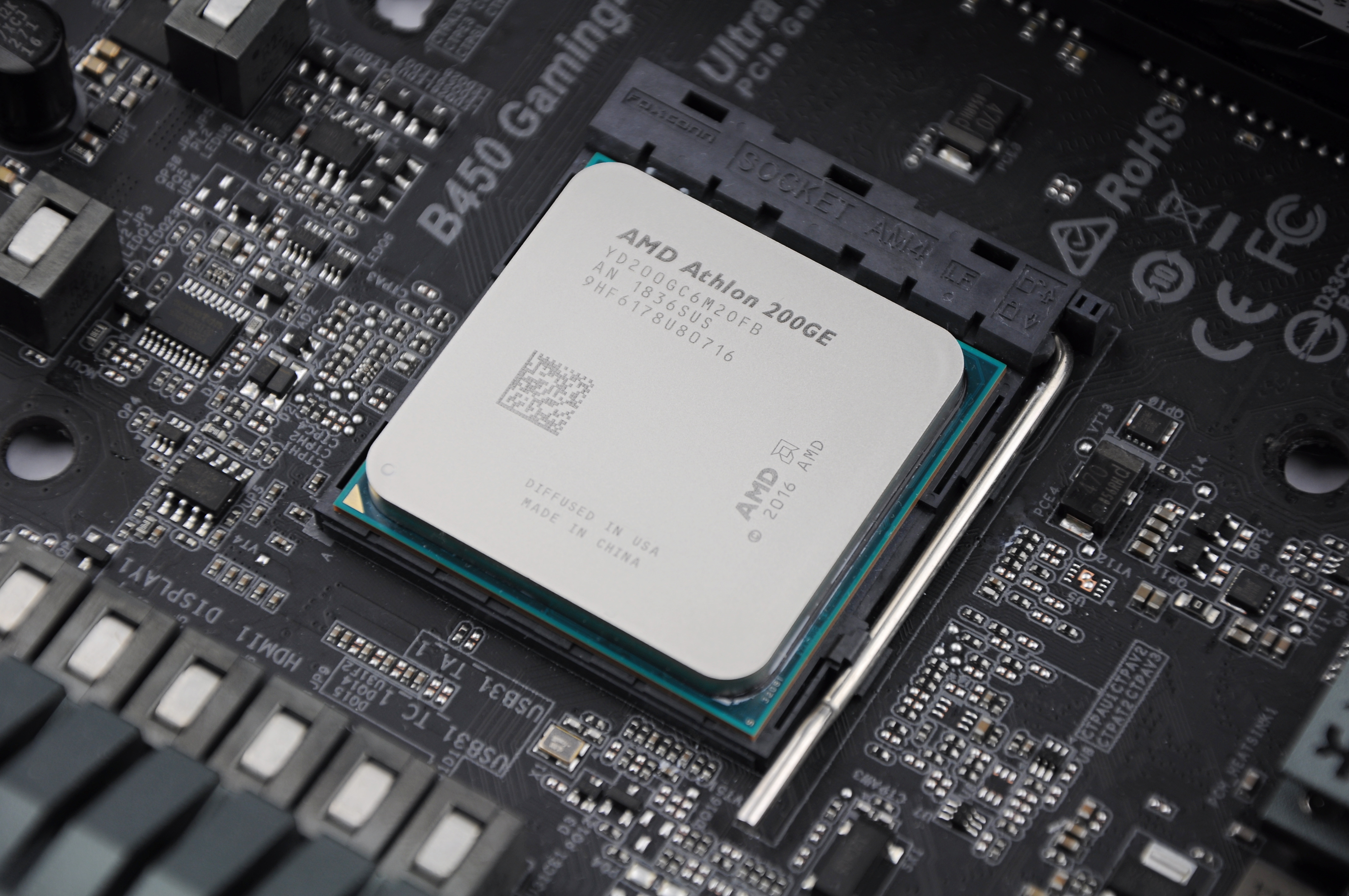
Processor orientation is also often indicated by a triangle (symbolizing an arrow) in the corner, which corresponds to the similarly marked corner on the socket. It may be marked on the top or bottom side of the processor substrate. The socket has a corresponding triangle, typically on the plastic carrier where the processor sits; with Socket AM5, it is also sometimes marked on the metal carrier around the plastic part, visible after lifting the cover.
Always be Mindful of LGA Socket Protection
If you have a board with an LGA-type socket (AM5 boards for AMD processors and all boards for Intel processors), where the pins are on the board, exercise great caution when handling it. Place the processor into the open socket slowly and deliberately, and close the metal cover only when you see that it has properly seated in the plastic carrier (always perform this with the board placed horizontally!). Avoid letting the processor drop a corner into the pin field or fall onto the socket.
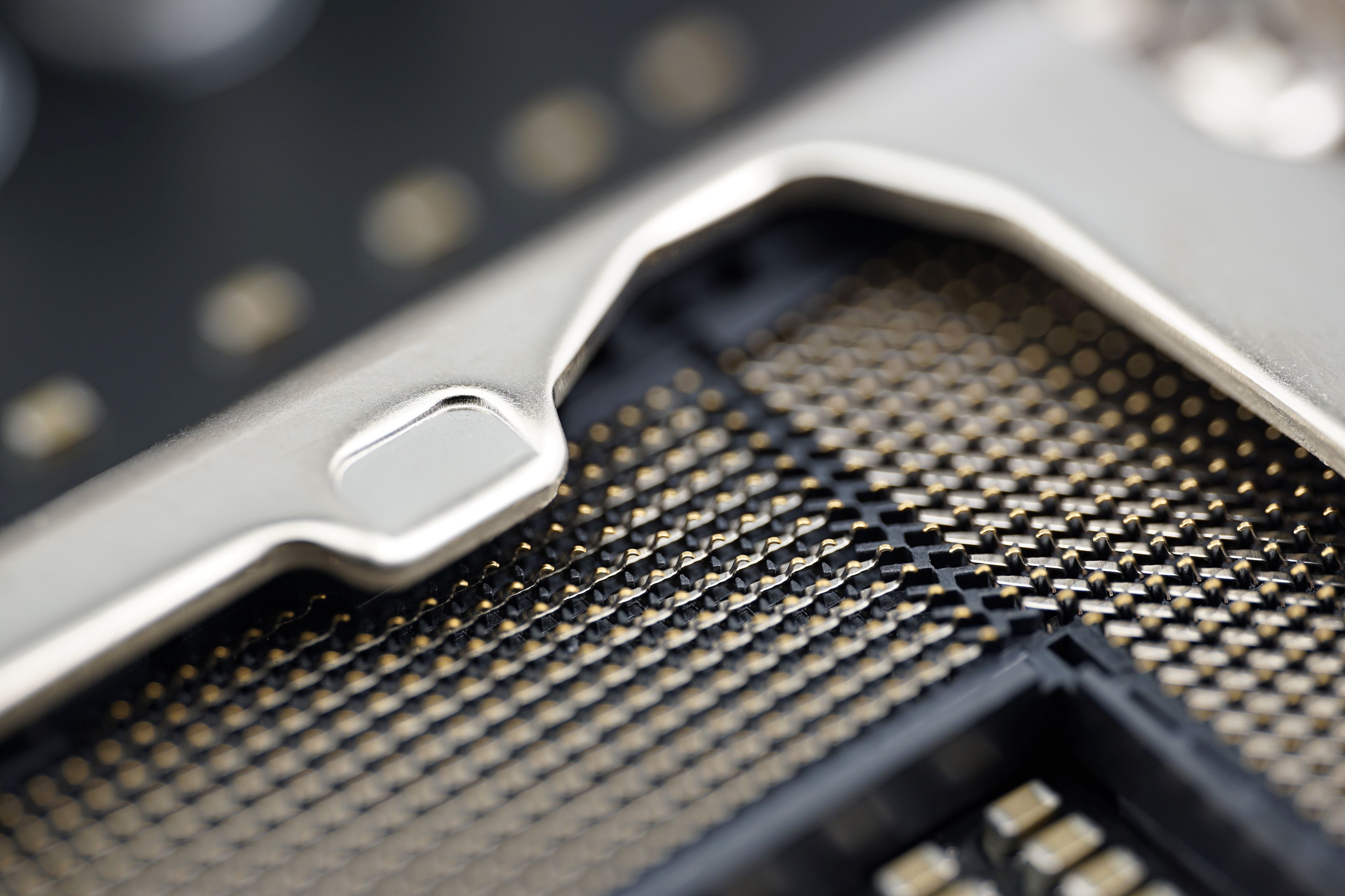
Any pressure on the socket’s pins can seriously damage it, whether you do it with a finger, a corner or edge of the processor, or if something falling inside. The pins are very fine, intricately shaped, and extend from the socket at an angle, not vertically and straight. It is therefore difficult to straighten them correctly if you bend them (breaking them is likely fatal damage, unless it happens to be a redundant pin; additionally, there is a risk of shorting two pins upon contact, which can damage the CPU). Caution here is therefore really important; it will save you a lot of frustration and often money. Well-equipped service centers can replace the socket, but it will be a relatively expensive repair.
Boards with LGA-type sockets come from the factory with a plastic cover placed on the socket to protect it. Remove it only just before installing the CPU, precisely to prevent accidental damage. If you remove the processor and store the board, for example in a box, put the protective cover back on. Therefore, do not throw away this piece of plastic and keep it safe somewhere where you’ll find it if needed.
If you are removing a board with an LGA socket from an existing computer, ideally you should find and install the corresponding cover for its socket type. If this is not possible, try to use at least some temporary solution to cover the socket, but be careful that it cannot come loose and somehow interfere with the pin field. The original plastic cover should always be installed whenever you are shipping the board—if there is anything loose in the package, it could travel in the box, hit the socket pins, and damage them. Socket pins bent or otherwise damaged during shipping are unfortunately a common incident for LGA boards. Even the socket cover coming loose inside the box and rattling around could cause damage. When packaging boards, try to ensure the cover has no chance to do so.

Older motherboards with PGA-type sockets, where the pins are on the processor and you only have holes in solid plastic in the socket (this type is used today by AM4 boards), do not require as much caution and care during assembly and transport with regard to mechanical damage.
However, for both socket types, including PGA, be careful not to get thermal paste inside. It will be very difficult to clean out and can cause problems. Contamination of contacts with non-conductive paste can interfere with proper function, while conductive materials risk short circuits and thus potentially damaging expensive hardware. Again, it pays to work carefully, deliberately, and avoid haste. If paste squeezes out sideways or gets dangerously close to the socket somewhere, stop working and carefully remove it. Be careful not to inadvertently smear the escaped drop or blob inside with a careless or awkward movement.
Read more: How it works in an Asus service center
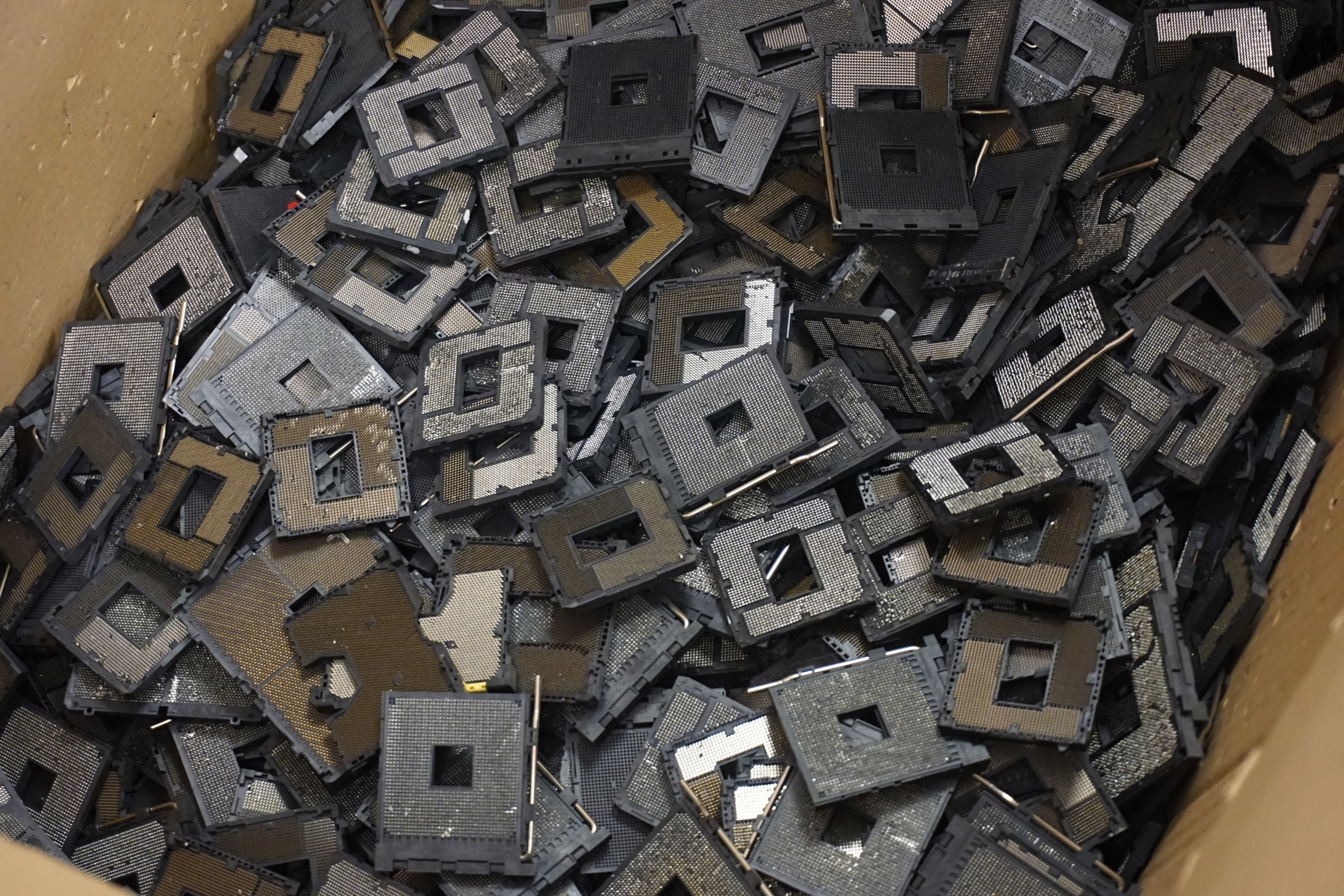
„The most common errors of motherboards are a damaged socket or broken pins. This applies to all Intel platforms and, in case of HEDT, AMD, too. This is confirmed by the cemetery of sockets in the photo below. However, individual pins are not repaired and sockets are completely replaced with new ones. In some centers, they are said to be repaired at the pin level, but that’s some tough job. Especially when a motherboard is returned several times in a row from the same customer who is obviously wrong when installing a processor.“
Common Assembly Mistakes
Make sure you don’t forget to install the standoffs in the case on which the motherboard should sit. Without them, it will not be in the correct position relative to the slot covers and rear ports, it may flex, and could potentially short-circuit against the case metal. If a required position lacks a threaded hole, you can use plastic standoffs with a smooth base that just rest on the metal, while the board is held by screws elsewhere.
Some cases are an exception; instead of threads for standoffs, they have the motherboard tray shaped so that the standoffs are integrated—the metal is raised at those points to form a threaded bulge for the mounting screw itself. In this case, the board is installed directly into the case without standoffs.
Mounting screws are installed on boards without using washers. There are usually exposed contact pads on the PCB around the mounting holes, and the intention is for the screw to provide grounding to the case frame through them, so using washers would be counterproductive.
Be careful not to over-tighten the screws. Theoretically, you could damage the PCB with excessive pressure, though this is probably unlikely. Generally, when installing, removing, or tightening screws, be careful not to damage nearby components with the screwdriver, as they can be fragile. It is ideal to use a screwdriver with a sufficiently magnetized tip so the screw doesn’t fall off. Typically, a screw falling among components on the board won’t cause harm, but if it falls into an LGA socket, it could cause very unpleasant deformation or damage to the pins, which is difficult to fix, as mentioned previously.
A less dangerous mistake that builders sometimes make is forgetting to install the rear I/O shield. You need to install it (and clip it firmly in place) into the case opening before inserting the board into the case. Newer boards often have the shield permanently attached from the factory, eliminating this concern. The computer can function without this shield, but it’s not just a cosmetic issue—without it, a user could reach inside while handling ports and short something out.
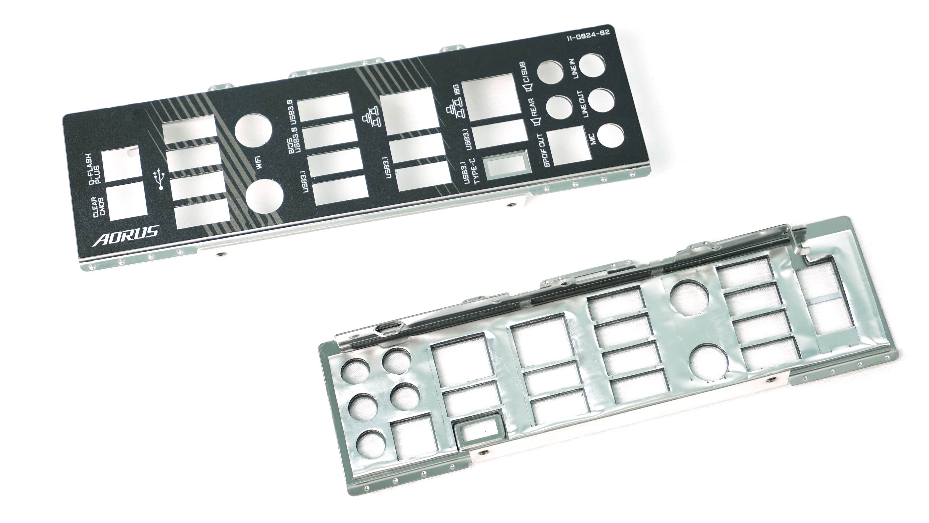
Theoretically, problems can also arise with proper grounding of ports during handling, to which the metal shield contributes, although the board itself should already handle this. For example, if a pre-owned used motherboard is missing its I/O shield, try to find a replacement (the downside is that these shields are specific to different models, so you need to find the correct type; visual similarity alone may not be enough, as the cutout positions might differ by a few milimeters, which is enough to make the ports unusable). An alternative is to 3D print a corresponding piece.
English translation and edit by Jozef Dudáš
⠀