


This is a first – a fan with the leading edges of the impeller blades on the opposite side to normal ones. This is primarily done for a better view of “fans without stator struts” in cases with glass side panels. In addition, such an unconventional design also has quite clear and measurable advantages and disadvantages, also in terms of functional characteristics. Let’s take everything in turn.
Everything changes with obstacles
So far, we have described how static pressure and airflow measurements are made under conditions where the fan has no obstacles in its path. In practice, however, fans do not usually blow into an empty space, but have a filter, grille or radiator in front of or behind them, the fins of which need to be pushed through as efficiently as possible.
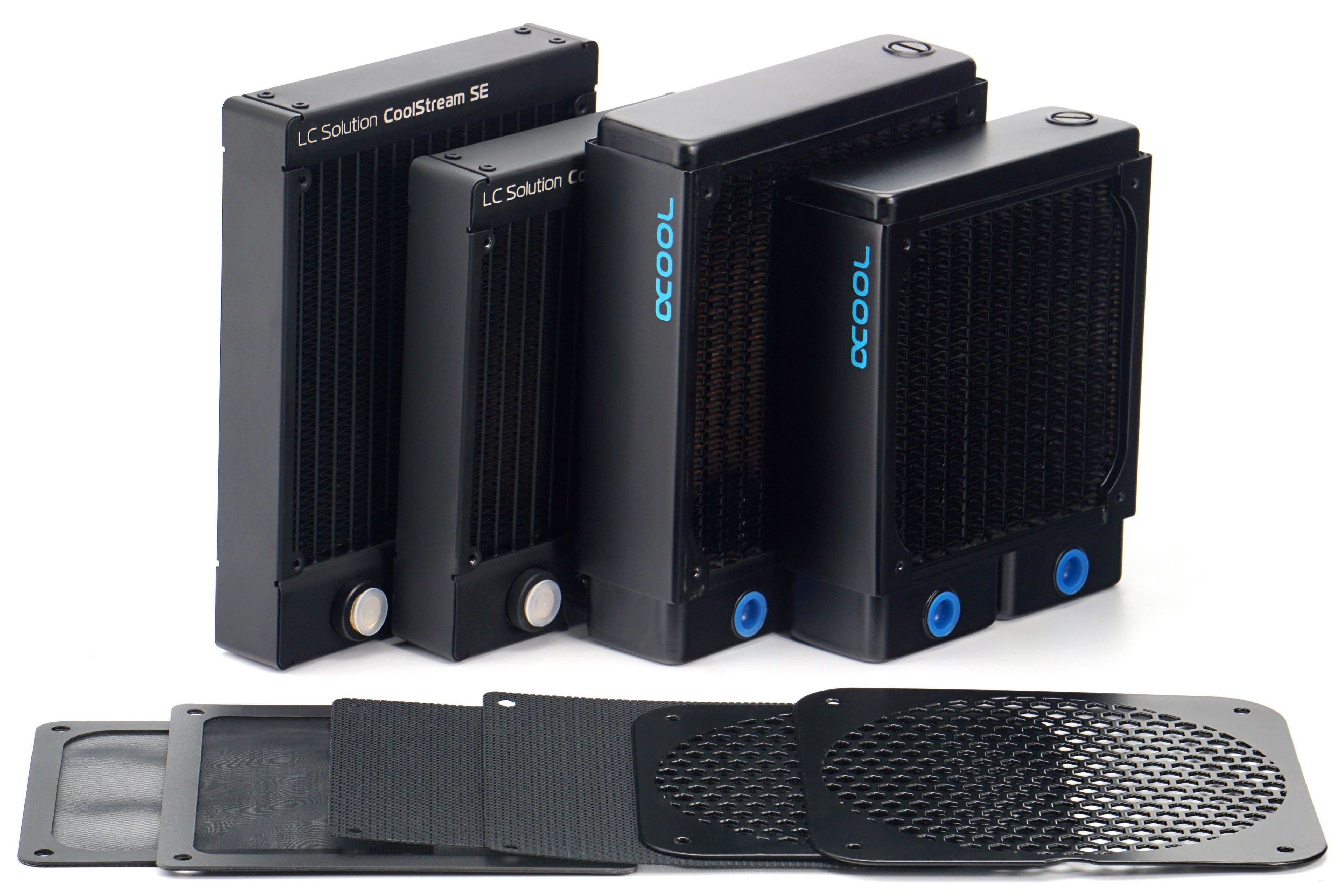
We will also measure both airflow and pressure through practical obstacles for the reasons stated above. These include two types of filters that are usually used in PC cases. One fine – nylon and the other plastic with a thinner mesh. One other obstacle is the hexagonal grille perforated at 50%, on which the vast majority of fans – intake and exhaust – are installed. In some cases, we measure the effect of the obstacles on the results at positions (behind or in front of the impeller) that are used in practice. All obstacles are both pushed through to detect pressure drops, but also pulled through, which in turn speaks to the impact on airflow.

We use two radiators that differ in thickness and fin density. The EK CoolStream SE120/140 is 28 mm thick and the FPI is 22, the Alphacool NexXxoS XT45 v2 is thicker (45 mm) but with less FPI. CoolStream’s fin disposition is also similar in parameters to AIOs. The results on the NexXxoS will again be attractive for those who build their own water cooling loops, where the fans should work well even at low speeds – hence the lower fin density.
These obstacles and especially the radiators, but also the grilles, increase the mechanical resistance in front of the fan, resulting in higher noise levels. However, we will still tune the fan speeds to the specified noise levels of 31 to 45 dBA. Naturally, the speeds will always be lower than when testing without obstructions, but we will maintain the noise levels for clarity. The different noise levels with and without obstacles will only be at maximum power. In this mode it will also be nice to see how the fan design works with the obstacle and in which case the noise level increases more and in which less.



Any plans for tests of the non-reverse variant, and also spacers (like Noctua NA-IS1)? To me they would be the logical next steps for topics raised in this test.
We do not plan to test the standard variants of TR120 fans in the near future. In the long run, the basic plan remains the same – we have to compare all the fans that exist, haha. Only time will tell where we will really end up. 🙂
We’ve had the NA-IS1 frames in our editorial office since their introduction. Of course it would be really useful to get to them and one day it will come. I still can’t make space for them – there is always something “more important”.
Always looking forward to your tests, whatever they are🙂
One additional question though, could you further elaborate what’s going on with the hexagonal grille tests for this fan? First time I’ve seen a fan that somehow has parts of the data missing in the middle (33 and 36 missing, but not 31 and 39). You say unstable tonal peaks, so is the RPM unstable at those noise levels, or is it due to something else?
I think it’s happened before. But maybe it was for the quietest or loudest mode of normalised noise and then it can be attributed to another reason? Anyway, I will explain.
It is important to realize how we bring the fans to the “same noise level”. It’s not like we set the fan somehow and it’s stable at, say, 36 dBA. It’s that we set the fan so that the average of 30 samples ends up at 36 dBA. The interval of these samples can be in the range of 35,9–36,1 dBA during the measurements, for example, but possibly also in a much wider range, for example 32–38 dBA, and now I am not exaggerating. This latter case is similar to trying to get the TR120 into the 33 and 36 dBA modes, which failed. With no PWM setting (nor after very fine tuning of the pulse strength with voltage in single digits of mV), we could not set the fan on the grille so that the average of 30 samples corresponds to 33 dBA and 36 dBA, respectively. It was always more or less, i.e. not what was required. This is a topic that certainly makes sense to look at in more detail. Especially after Noctua opened this “Beat frequency theory” topic, which is a good basis for understanding the issue by a wider than very narrow spectrum of users.
–“Beat frequency theory”
…well, already during the 1st world war the company on the bridge had to stop marching in order not to shake the bridge.
Wave interferance
https://en.m.wikipedia.org/wiki/Wave_interference
In acoustic
https://en.m.wikipedia.org/wiki/Beat_(acoustics)
Thanks for your detailed explanation. The only other time I have heard the need of averaging noise samples is from ThermalLeft. What’s the sampling rate you’re using?
This phenomenon is definitely worth looking into some day, especially for instances like this where large deviations occur.
The sampling rate of the Reed R8080 is 1s. The settings for the individual modes normalized according to a fixed noise level are based on the arithmetic mean of a 30-second recording. This must always be exactly 31.0; 33.0; 36.0; 39.0; 42.0 or 45.0 dBA after rounding.