


To write that we have something mapped out to the last detail is perhaps too bold, but after proper preparation, few pieces of hardware are as easy to evaluate as fans. Of course, this had to be preceded by long preparations, developing a methodology, but you already know the story. What you don’t know yet is the first fruit, or rather the results of Akasa, SilentiumPC, SilverStone, Xigmatek or more exotic Reeven fans.
… and airflow
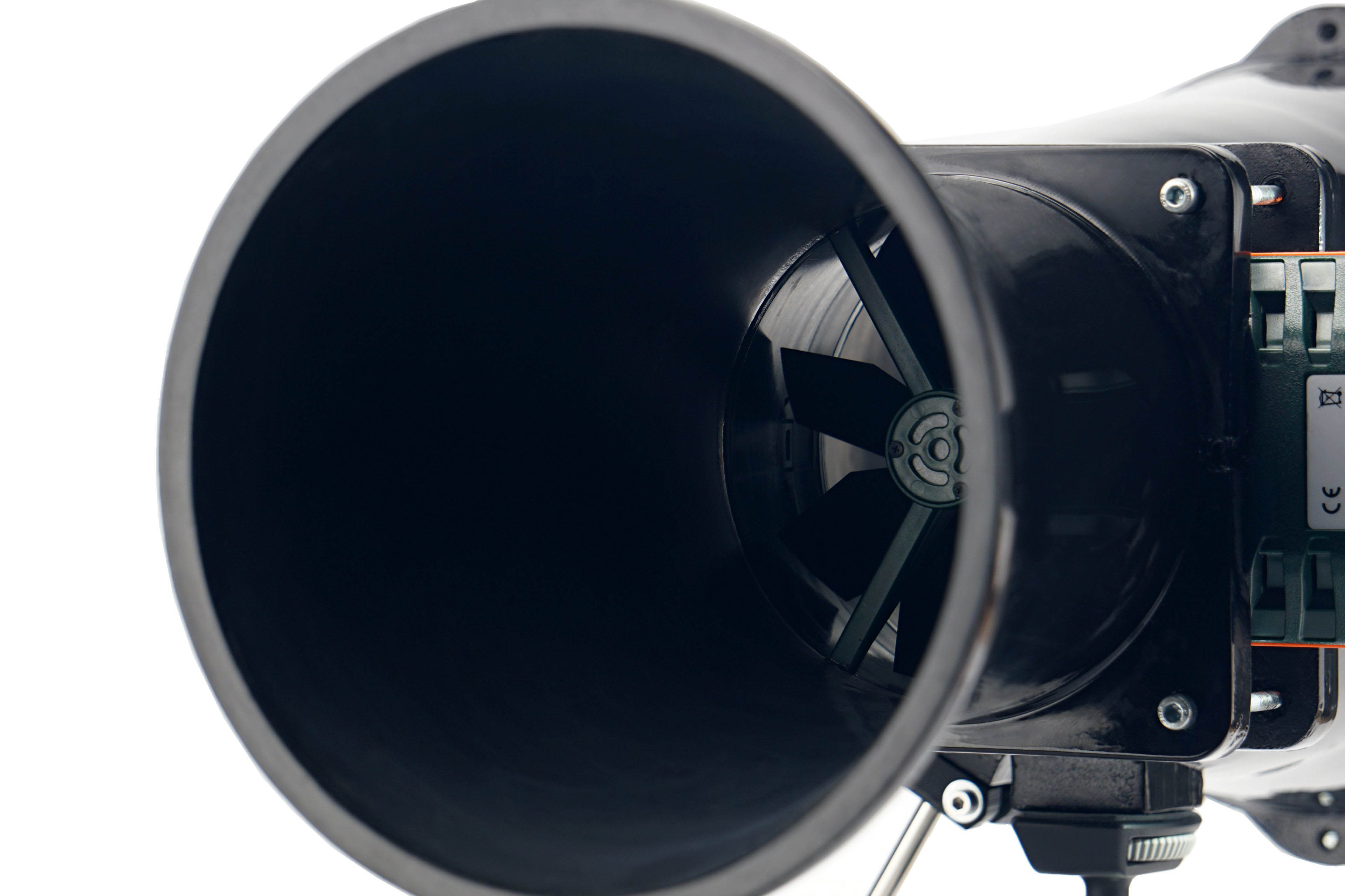
With airflow measurements, we can well explain why the test tunnel is shaped the way it is. It doesn’t consist of two parts just so that the “exhaust” can be conveniently clogged for pressure measurements. The anemometer (i.e. the wind speed measuring instrument) is held together by two parts, two formations, through the flanges.
The front part, at the beginning of which the fan is mounted, becomes steadily narrower and from about two thirds of the way through the cross-section is smaller than that of a 120 mm fan. The reason for this is that the cross-section of the anemometer is always smaller than that of the fans tested. The taper towards the anemometer fan is as smooth as could be chosen and the tunnel walls are smooth. This has minimized the occurrence of unnatural turbulence.
The difference between the cross section at the intake (fan under test) and at the constriction point (anemometer) also means a difference in dynamic pressure, the principles of the Venturi effect apply here. In order to avoid distortion at this level and to ensure that the fan airflow is not different from what it actually is, the Bernoulli equation must be applied to the measured values (for maximum accuracy, the calculation also takes into account the internal cross-sectional area of the anemometer, i.e. its inactive part ). After all this, it is again possible to confront our results with the paper parameters.
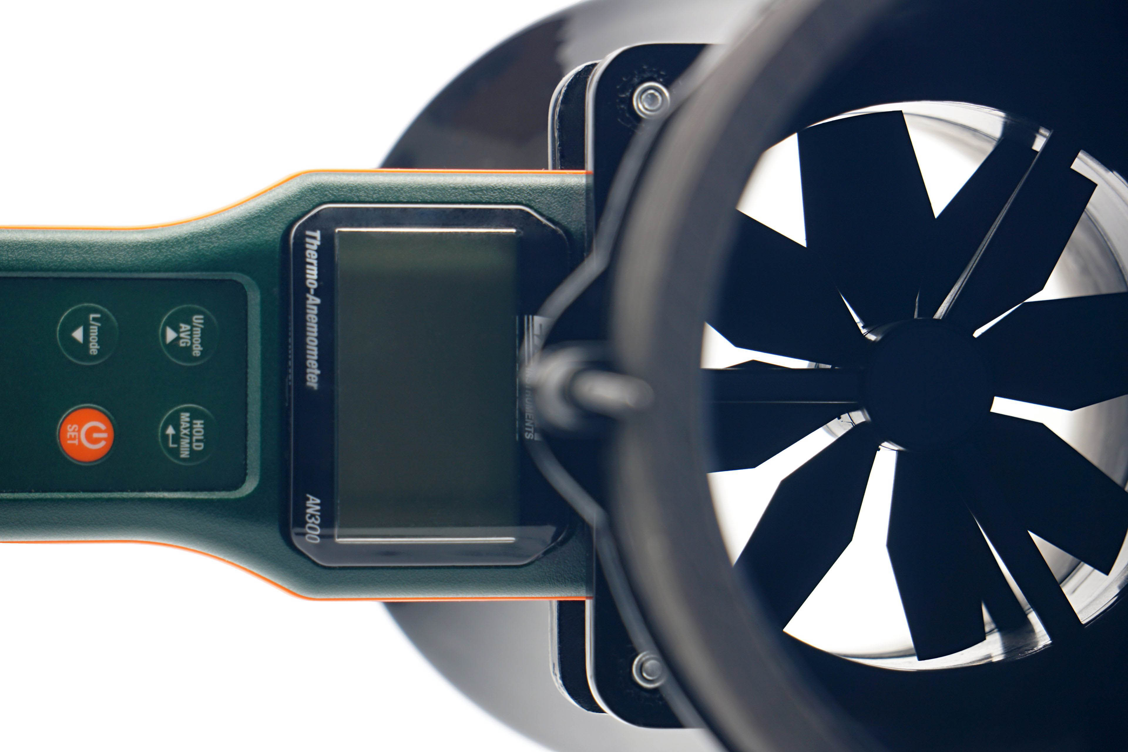
We use an Extech AN300 anemometer with a large 100 mm fan for the measurements. Its big advantage over other anemometers is that it is made for bidirectional sensing. This allows tests at different fan orientations. However, the “pull” position is more suitable or accurate for measurements, even though it may not seem so at first glance, but we’ll explain.
Here, we get to the second part of the tunnel, the part behind the anemometer. It is part of the whole device, mainly to allow a laminar flow of air to arrive at the rotor of the anemometer. Otherwise, uncontrolled side whirls would be reflected in the results, which are inconsistent with accurate measurements. Therefore, we will test the flow in the pull position. If anyone would like us to elaborate more on this topic, we can elaborate further at any time in the discussion below the article. Ask away. 🙂
In connection with the anemometer, we will return a little more to the noise measurements and to the setting of modes according to fixed noise levels. It may have occurred to you as you were reading that the anemometer fan is also a source of sound that needs to be filtered out when testing fans. For this reason, we insert a belay pad between the frame and the anemometer fan before each measurement and mode setting according to the fixed noise level.




Thank you so much for this! I thought that I might have just gotten a bad batch with my CM AIO cooler. Although, in my case, it’s not rattling but an uneven hum that keeps going up and down.
And thanks to your other reviews, I ordered some Noctua NF-A12x25 today. That’ll hopefully solve that. All of my other fans are Noctua too and while not all the new and best, they at least produce steady noise.
Using Noctua NF-A12x25 fans will definitely solve the issue you’re describing. The sound of the tested Cooler Master fans can be perceived differently by everyone. It’s certainly not clean in terms of aerodynamics. There’s absolutely nothing wrong with your ears. 🙂
Yeah, I’m very happy with the A12x25s! Skimming the Noctua website also reminded me that based on their description, what I heard may have been that “beat frequency”. They of course took care of that with the RPM offset in their 2x package.
Using different motors to achieve different RPMs under the same PWM signal is indeed a clever trick to reduce noise while maintaining strong airflow and cooling performance. 🙂