


The range of 140mm fans is now expanded by the Noctua NF-A14x25 G2 PWM. The wait for this model was very long, but finally, after various hardships, everything was brought to a successful end. This, by the way, is also indicated by our in-depth tests, from which the NF-A14x25 G2 fan takes away the “best” results across many usage scenarios. This is also due to the significant innovations in the aerodynamic design.
… and of airflow
With airflow measurements, we can well explain why the test tunnel is shaped the way it is. It doesn’t consist of two parts just so that the “exhaust” can be conveniently clogged for pressure measurements. The anemometer (i.e. the wind speed measuring instrument) is held together by two parts, two formations, through the flanges.
The front part, at the beginning of which the fan is mounted, becomes steadily narrower and from about two thirds of the way through the cross-section is smaller than that of a 120 mm fan. The reason for this is that the cross-section of the anemometer is always smaller than that of the fans tested. The taper towards the anemometer fan is as smooth as could be chosen and the tunnel walls are smooth. This has minimized the occurrence of unnatural turbulence.
The difference between the cross section at the intake (fan under test) and at the constriction point (anemometer) also means a difference in dynamic pressure, the principles of the Venturi effect apply here. In order to avoid distortion at this level and to ensure that the fan airflow is not different from what it actually is, the Bernoulli equation must be applied to the measured values (for maximum accuracy, the calculation also takes into account the internal cross-sectional area of the anemometer, i.e. its inactive part ). After all this, it is again possible to confront our results with the paper parameters.
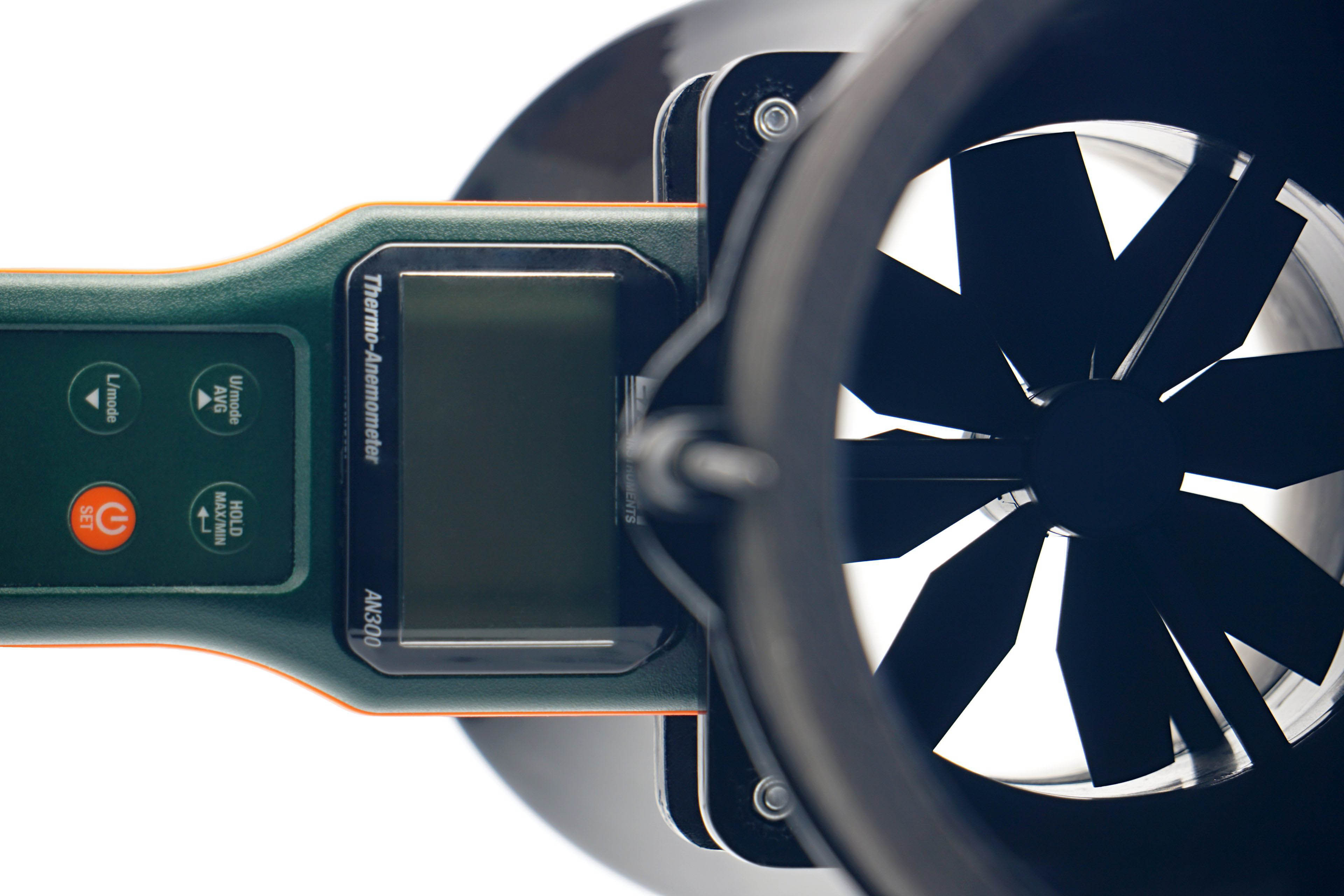
We use an Extech AN300 anemometer with a large 100 mm fan for the measurements. Its big advantage over other anemometers is that it is made for bidirectional sensing. This allows tests at different fan orientations. However, the “pull” position is more suitable or accurate for measurements, even though it may not seem so at first glance, but we’ll explain.
Here, we get to the second part of the tunnel, the part behind the anemometer. It is part of the whole device, mainly to allow a laminar flow of air to arrive at the impeller of the anemometer. Otherwise, uncontrolled side whirls would be reflected in the results, which are inconsistent with accurate measurements. Therefore, we will test the flow in the pull position. If anyone would like us to elaborate more on this topic, we can elaborate further at any time in the discussion below the article. Ask away. 🙂
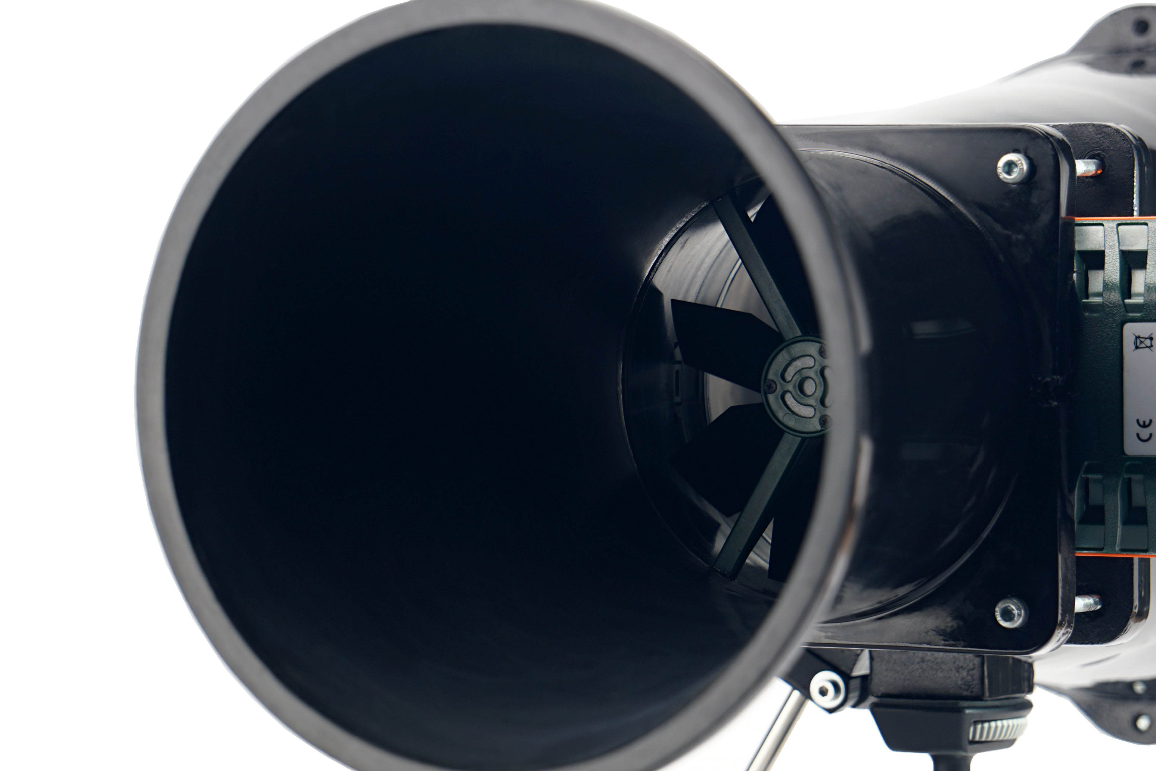
In regard to the anemometer, we shall return for a bit to noise measurements and to setting modes according to fixed noise levels. It may have occurred to you as you were reading that the anemometer fan is also a source of sound that needs to be filtered out when measuring fans. For this reason, we insert a securing pad between the frame and the anemometer fan before each measurement and mode setting according to the fixed noise level. This, by the way, also holds the anemometer fan during static pressure measurements.



Wow really a launch day review, is this a first for Noctua? 🙂
It will be the first time, yes. 🙂
Minor errors:
LS-PWM version is up to 800 RPM, not 1200.
Value’s missing in “Noise level – No obstacle – max speed” chart.
Question:
I remember Noctua saying that the protrusions on the gasket can compress enough to form a tight seal (based on my question)… guess not? Or is there not enough mounting pressure?
Thanks for the heads up, it’s corrected! 🙂
Yes, definitely, at different mounting pressures these protrusions in the anti-vibration gasket will compress differently, and in some cases they are compressed completely. As is the case in our situation on the thicker radiator. But there is still a gap on it. Caused by the way the walls of the radiator are rounded and the gasket is not perfectly straight and in places it twists a bit (you can see it well in this photo). It’s still just a soft liner, so it’s a natural thing. Don’t expect dramatic differences at this level though – the airflow through the radiator would be comparable even with an older system without the gasket material around the fan walls. Hmm… it’s maybe a good idea for a specific test looking at the dependence of the airflow on the presence of the gasket. Well, we’ll see…
I’ll test and see how well the gasket compresses once mine arrives. I’m guessing it might need pretty high mounting force to compress completely.
While the imperfect seal might only change the airflow by a few m3h, it seems enough to knock the fan from #1 to #2 at least in some cases. Case in point: no obstacle @ 36 dBA, Round = 810 RPM, 73.9 m3h; Square = 825 RPM, 72.1 m3h. The very slight difference in RPM should be due to the more substantial frame attenuating noise slightly more; meanwhile, the deterioration in airflow despite having higher RPM could only be attributed to increased leakage from the sides.
We will be glad if you share the results after your own tests. 🙂
I don’t have the proper equipment to test the exact force needed, but it seems to require pretty high mounting force indeed. I couldn’t compress it at all with my bare fingers, and in order to compress it on an acrylic panel, I needed unconformably high force (and still couldn’t get the sides to fully seal). For my application, foregoing antivirbation pads and gaskets altogether resulted in a much better seal. Fortunately, I have the intake side against the panel, and according to the manual that side does not need load relief.
Thanks for the info. The degree of deformation of these pads (and the size of the gap between the fan and the radiator) will be strongly dependent on the mounting pressure of the screws, which can vary even when fully tightened.
Such an achievement! Don’t forget, fellows.
Here is a selected comparison to the P14, dust filter and hexa grille.
Nice comparison with the fact that with your frame even better results are achieved. The offset from the obstacle is obviously useful. Microturbulence is suppressed, which reduces noise at the same time as the pressure/airflow is increased. Great, good work. 🙂
In a corsair 5000D where a 7800x3d is cooled by a noctua dh-15, which set of fans or fan configuration do you recommend me for optimal slightly positive pressure? Should i go for 2 front 1400mm, 1 rear 120mm and rear top 120mm? Thanks
One of the good options are Noctua NF-A14x25 G2 PWM fans. Then there are several alternatives that have a suitable aerodynamic design, but you need to know about the things that could possibly bother you. With the BeQuiet Silent Wings Pro 4 (BL099) it could be a whiny coil in PWM control, with the Arctic P14 Max it could be the minimum speed that’s too high, and with the Thermaltake Toughfan 14 Pro it could be the lower build quality (if you come across a clicking piece or multiple such pieces). Of the cheaper fans, the BeQuiet Pure Wings 3 (BL108) is still attractive, but it also has some weak points – check them out in our analysis and consider what is (in)essential for you.
Why did it fail so bad against a plastic filter compared to the previous gen? Are they not good for case intakes?
It is hard to say why there has been such a deterioration. The aerodynamic design of the two fans is significantly different. Some improvement could be achieved with a spacer, as indicated by the results of the NF-A14x25r G2 fan with the DIY frame, but in that case below average results are achieved. In cases with fans more significantly offset from the filters or with a thicker front panel structure, the Noctua NF-A14x25 G2 might already be suitable/top-notch, as can be seen in the results with the hexagonal grille. These are already significantly better than with the first generation fans (NF-A14 PWM).
Thanks for the test ! Time to try those on the North XL. <3
Planning to put 3 on the front and limit them at 1.000 rpm, hopefully they won't resonate with the front wood 😀
The vibration of the NF-A14x25 G2 PWM that reaches the frame is negligible at 1000 rpm. They will almost certainly not cause secondary noise on the front panel of the FD North XL. How the fans will interact with the structure of the brackets or the wood panel is, of course, another matter. Due to these elements, the acoustic profile can change even at lower speeds. Be sure to let us know how this combination of the case (FD North XL) and the fans (NF-A14x25 G2 PWM) behaves. 🙂
I was hoping to replace my 140mm radiator fans with these but, having seen your results, I don’t know that I would benefit from doing so. I have been using the Toughfan ex14 Pro and it seems to beat the NF-A14x25 G2 pretty handily in most of the radiator airflow tests. Am I missing something?
As far as cooling efficiency on radiators is concerned, it will be very similar for both fans. Nevertheless, it must be stated that the Toughfan Pro EX14 should not be lagging behind in this regard and rather will be the one that is more efficient (i.e. achieving a hair higher cooling performance at comparable noise levels). However, the premise that you don’t get to clicky pieces with the Toughfan Pro EX14 has to be met. This is something you probably won’t have to deal with with Noctua NF-A14x25 G2 fans, as the manufacturing quality requirements are higher.
I’m confused about those static pressure and airflow measurements. In your charts, the Arctic P14 (which is much cheaper) seems to beat the NF-A14x25 G2 at matched sound level. It produces higher static pressure against resistance, and more or comparable airflow.
So it seems that this premium fan isn’t that great in terms of static pressure, airflow or noise. Am I missing something?
Thank you for your question, I will be happy to explain.
It is not true that higher measured values of static pressure at the same airflow automatically mean a smaller loss of airflow through an obstacle. This may or may not be the case. One reason for this is that static pressure is measured at zero airflow, which represents significantly more resistance (and back pressure) than any obstacle in practice. The resistance of a radiator is also significantly smaller than the situation at which static pressure is measured. At zero airflow, the fan behaves differently than on an obstacle at non-zero airflow. At zero airflow, a different, practically unrealistic motor output is achieved, and so in the real world it is not possible to work responsibly with this value. In other words, a fan that has a lower static pressure at the same airflow (these values are in turn usually based on a zero static pressure environment, which is also out of common practice…) may not have a greater loss of airflow through an obstacle. Again: It can, it doesn’t have to. Meanwhile, how a particular fan interacts with a chosen obstacle also plays a role in tests normalized by noise level. Specifically, to what extent does a given obstacle increase the noise level of a particular fan. This can also vary from case to case. It depends on the combination of the particular aerodynamic design of the fan with the particular structure of the obstacle. While in some combinations there are no significant tonal peaks (compared to a situation without an obstacle), these are dramatic in some/other cases. It is individual. Anyway, to evaluate responsibly the aerodynamic performance of a fan for practical use based on traditional measurements of static pressure and airflow, and hence actually P/Q curves, is impossible. This is because practical measurements on obstacles, which are important, are lacking. For what reasons you already know. Does that answer your questions? If anything is unclear, feel free to bring it up, we can discuss the specifics again. 🙂