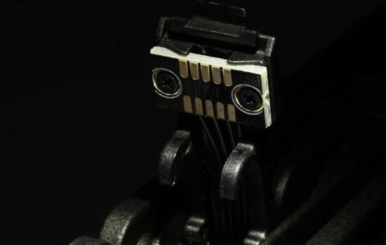
To write that we have something mapped out to the last detail is perhaps too bold, but after proper preparation, few pieces of hardware are as easy to evaluate as fans. Of course, this had to be preceded by long preparations, developing a methodology, but you already know the story. What you don’t know yet is the first fruit, or rather the results of Akasa, SilentiumPC, SilverStone, Xigmatek or more exotic Reeven fans.
How we measure power draw…
Is it worth addressing the power draw of fans? If you have seven of them in your computer (three on the radiator of the cooler and four for system cooling in the case) and they are also backlit, the power draw starts at tens of watts. This makes it worth dealing with.
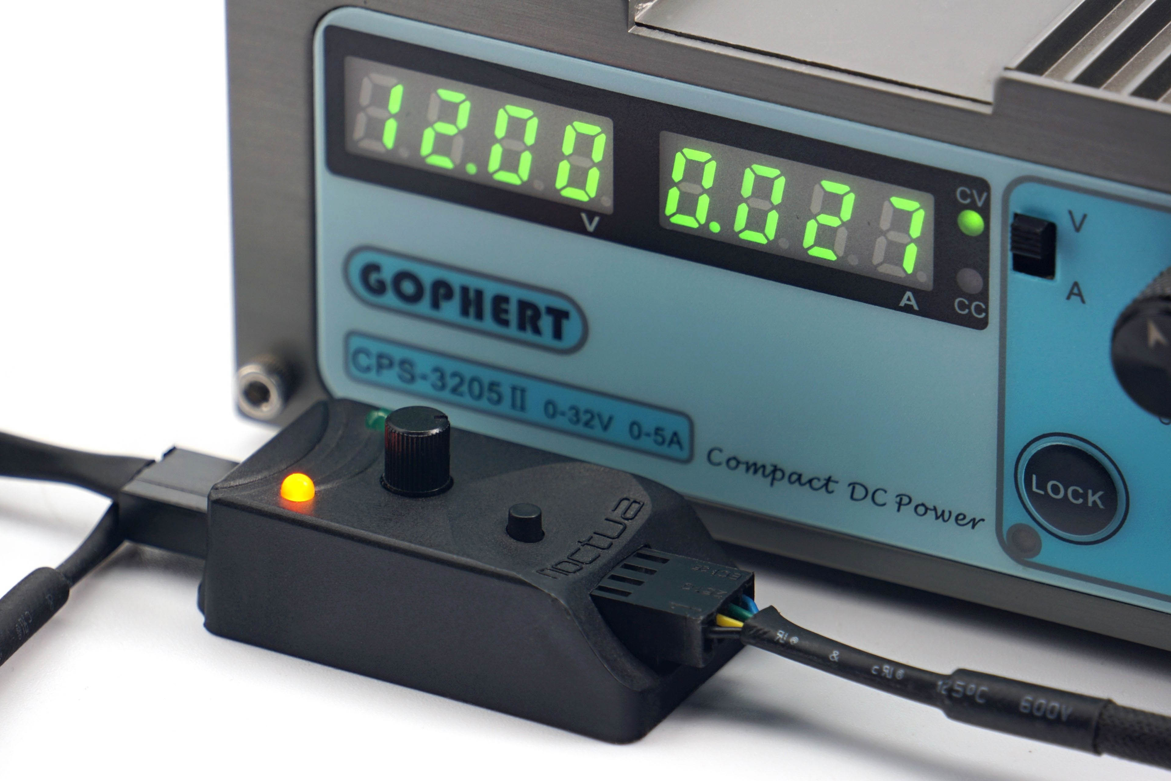
All fans are powered by Gophert CPS-3205 II laboratory power supply. It is passive and virtually noiseless, so it does not distort our noise level measurements. However, for the PWM fans, a Noctua NA-FC1 controller is connected through which the fans are regulated. We also have a shunt between the power supply and the Noctua controller. On it, we read the voltage drop, from which we then calculate the current. However, the voltage on the power supply is set so that 12 V goes to the Noctua NA-FC1. We then also set the exact 12 V to measure the maximum power of the 3-pin linear power supply fans.
In the power draw tests, we will be interested in the power draw in fixed noise level modes in addition to the maximum power consumption at 12 V or 100% PWM. That is, at those settings at which we also measure other parameters. Finally, in the graphs you will also find the power consumption corresponding to the start-up and minimum speeds. The difference between these two settings is that at start-up speed you need to overcome the frictional forces, so the power draw is always higher than at minimum speed. At these, the fan is already running and just reduces power to just before a level where it stops.

These start-up and minimum power draw data are a substitute for the start-up and minimum voltage information. You often encounter this when reading about fans, but with PWM fans there is no point in dealing with it. And although it is possible to power a PWM fan linearly, it will always perform better with PWM control – lower starting and minimum speeds. Therefore, it would be unfair to compare these parameters for all fans using linear control. That way, fans with PWM would be disadvantaged and the results distorted.
…and motor power
In addition to power draw, it is important to consider one more parameter that is related to the power supply – the power of the motor. This is usually listed on the back on a label and is often mistaken for power draw. However, the voltage and current indication here is usually not about power draw, but about the power of the motor. The latter must always be well above the operating power draw. The more, the longer the life expectancy of the fan.
Over time and with wear, fan friction increases (through loss, hardening of the lubricant, dust contamination or abrasion of the bearings, etc.). However, a more powerful motor will overcome the deteriorating condition of the fan to some extent, albeit at a higher power draw, but somehow it will cope. However, if the difference between the motor power and the operating power draw of the new fan is small, it may no longer be able to exert sufficient force to turn the rotor under increased friction due to adverse circumstances.

To test the power of the motor, we set the fan to full power (12 V/100 % PWM) and increase the mechanical resistance by braking the rotor in the middle. This is a higher load for the motor, with which the power draw naturally increases. But this is only up to a point, until the rotor stops. The power of the motor in our tests corresponds to the highest achieved power draw that we observed when the fan was being braked.
We use the Keysight U1231A high sample rate precision multimeters to analyse motor performance (as well as normal operating power draw). In addition, the individual samples are recorded in a spreadsheet, from which we then graph the maximum. The final value is the average of three measurements (three maximums).