




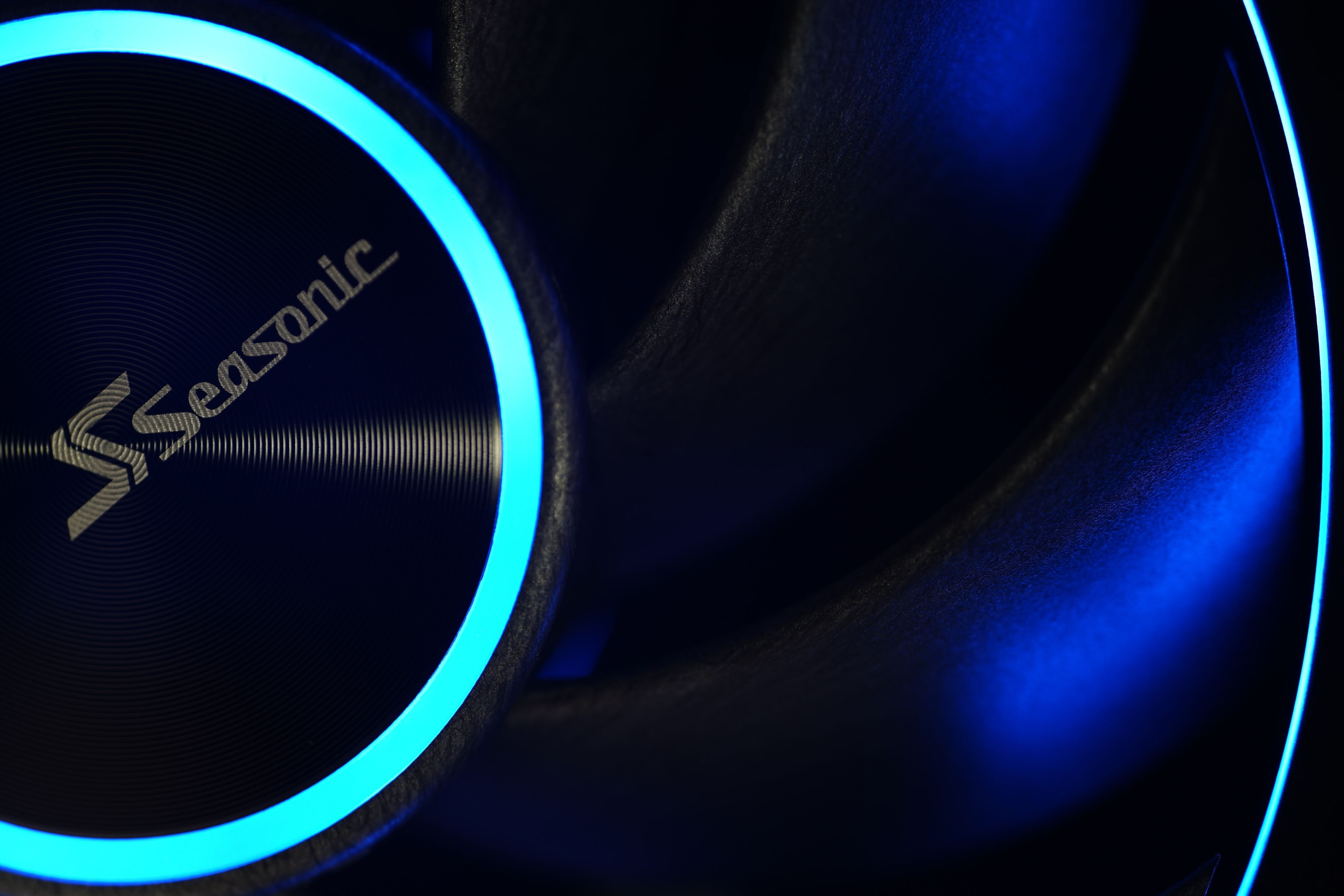
A concept in which an LCP impeller and ARGB LEDs meet is particularly rare. But it has enormous potential for achieving top-notch results. That is, as long as everything fits together optimally and there are no weak spots somewhere that increase the noise level. There are still a few things to tweak with the MagFlow ARGB fan, but already now, in its current form, it is a premium fan, and not only among lighted models.
… and of airflow
With airflow measurements, we can well explain why the test tunnel is shaped the way it is. It doesn’t consist of two parts just so that the “exhaust” can be conveniently clogged for pressure measurements. The anemometer (i.e. the wind speed measuring instrument) is held together by two parts, two formations, through the flanges.
The front part, at the beginning of which the fan is mounted, becomes steadily narrower and from about two thirds of the way through the cross-section is smaller than that of a 120 mm fan. The reason for this is that the cross-section of the anemometer is always smaller than that of the fans tested. The taper towards the anemometer fan is as smooth as could be chosen and the tunnel walls are smooth. This has minimized the occurrence of unnatural turbulence.
The difference between the cross section at the intake (fan under test) and at the constriction point (anemometer) also means a difference in dynamic pressure, the principles of the Venturi effect apply here. In order to avoid distortion at this level and to ensure that the fan airflow is not different from what it actually is, the Bernoulli equation must be applied to the measured values (for maximum accuracy, the calculation also takes into account the internal cross-sectional area of the anemometer, i.e. its inactive part ). After all this, it is again possible to confront our results with the paper parameters.
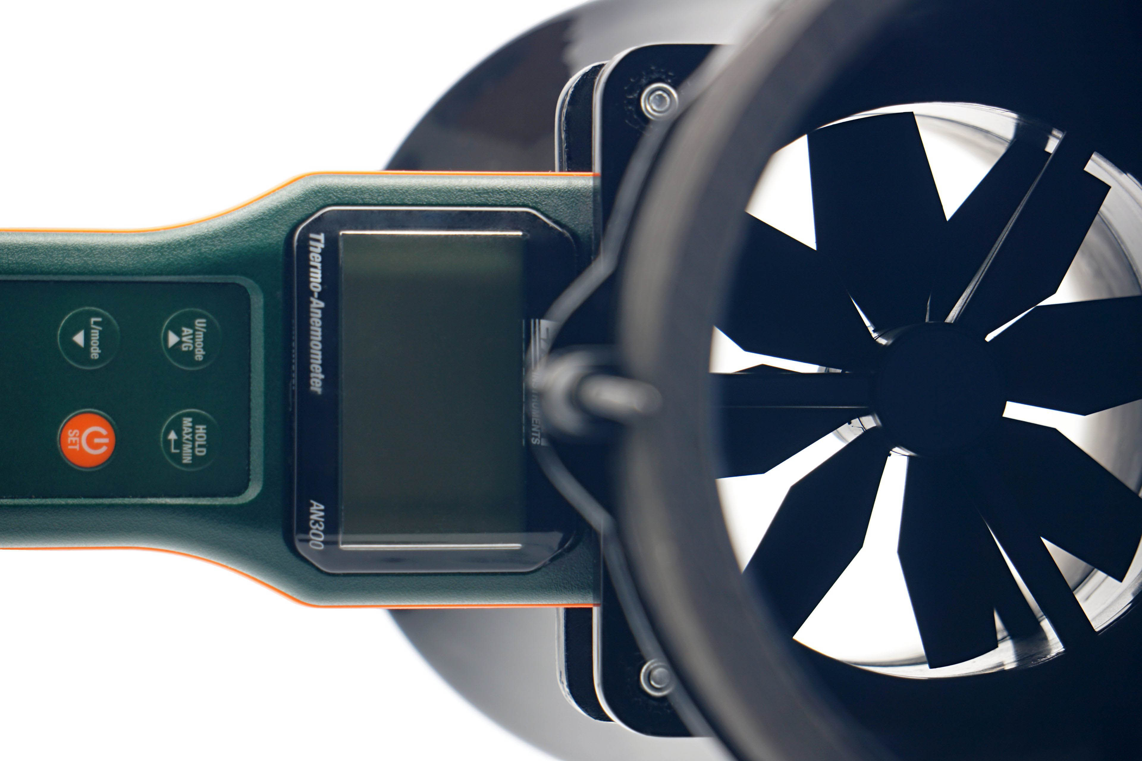
We use an Extech AN300 anemometer with a large 100 mm fan for the measurements. Its big advantage over other anemometers is that it is made for bidirectional sensing. This allows tests at different fan orientations. However, the “pull” position is more suitable or accurate for measurements, even though it may not seem so at first glance, but we’ll explain.
Here, we get to the second part of the tunnel, the part behind the anemometer. It is part of the whole device, mainly to allow a laminar flow of air to arrive at the impeller of the anemometer. Otherwise, uncontrolled side whirls would be reflected in the results, which are inconsistent with accurate measurements. Therefore, we will test the flow in the pull position. If anyone would like us to elaborate more on this topic, we can elaborate further at any time in the discussion below the article. Ask away. 🙂
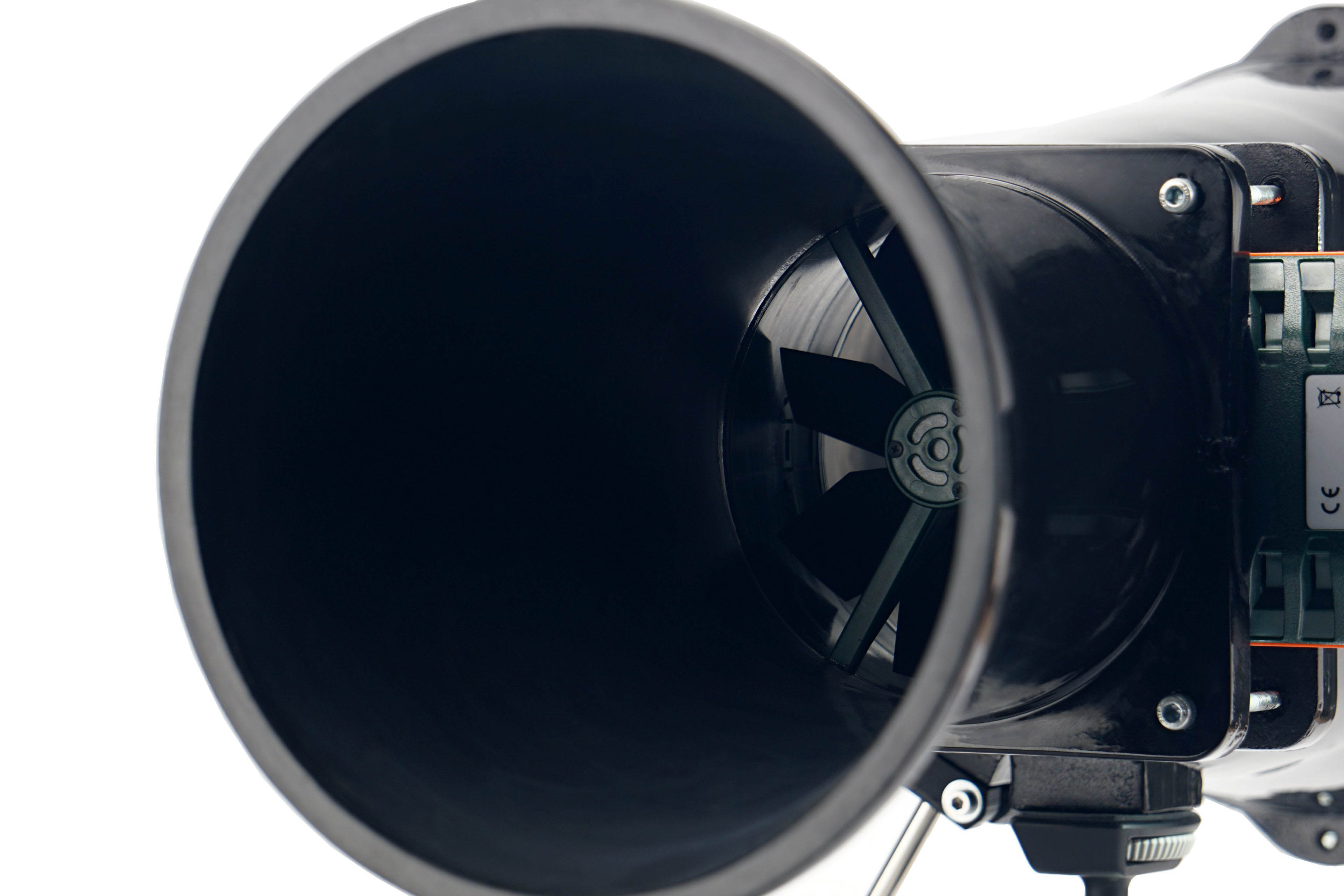
In regard to the anemometer, we shall return for a bit to noise measurements and to setting modes according to fixed noise levels. It may have occurred to you as you were reading that the anemometer fan is also a source of sound that needs to be filtered out when measuring fans. For this reason, we insert a securing pad between the frame and the anemometer fan before each measurement and mode setting according to the fixed noise level. This, by the way, also holds the anemometer fan during static pressure measurements.




Hmm, that’s worse than I thought for an LCP fan with Gentle Typhoon-like rotor, only trading blows with the much cheaper Arctic P12 ARGB. Perhaps the impeller footprint is the main culprit here, alongside the motor and bearing.
Comparison with the Grand Tornado would be interesting, as they represent two extremes of impeller footprint while having similar blade geometry.
Yes. Thank you for the heads-up, we have added one more negative to the +/- table, namely that the vibrations at some speeds are higher than they could be for the standards of LCP fans. There is probably some imperfection at the level of the bearings, for which this happens in combination with this impeller.
I have no doubt that the impeller itself will be well aligned and the fault will be elsewhere. At the same time, it won’t be some random thing, as these fans behave identically across different samples. It’s hard to say where exactly the weak point is, but maybe it could be suppressed or compensated for in some way. For example with balancing inserts, like the Phanteks T30. And maybe they wouldn’t help at all, there’s probably no point in speculating here and you just have to accept the fact that the vibrations can sometimes be higher for an LCP fan than one would expect.
Still, this is only Seasonic’s second fan and I have no doubt that with each new one more and more flaws will be removed and eventually the result will be very positive. We gave them a tip for an “Arctic P12 with an LCP impeller”. Personally, I would be very interested to see how such a design, with a very precise build, would stand up to, for example, the NF-A2x25 or the T30. I guess it might not be a bad thing, since even the P12, with its noisier low frequencies, which could be significantly suppressed after blade stiffening, ends up at the top of the performance charts. The question is whether with a significantly heavier impeller the small hub could be retained, as it could probably cause some instability.