


The impeller is oriented so that, in the installed position, nothing visually obstructs the view. This refers to the stator struts, which can otherwise “spoil” the appearance. But this is not just about looks—it is about combining them with the efficient geometry of the proven five-blade design with a stabilizing ring (familiar from the P12 A-RGB). It is not exactly the same design, though, if only because what used to be behind the impeller is now in front of it.
Basis of the methodology, the wind tunnel
Before you start reading the methodology with all the details, take a look at the test tunnel as a whole. This is the heart of the whole system, to which other arteries are connected (manometer, vibrometer, powermeter, …). The only solid part of the tunnel from the measuring instruments is the anemometer.
The shape of the wind tunnel is inspired by the Venturi tube, which has long been used to measure the flow of liquids and gasses. The Venturi effect for wind speed measuring is also known from the aerospace industry. However, the design for measuring computer fans has its own specificities, which this proposal of ours reflects.
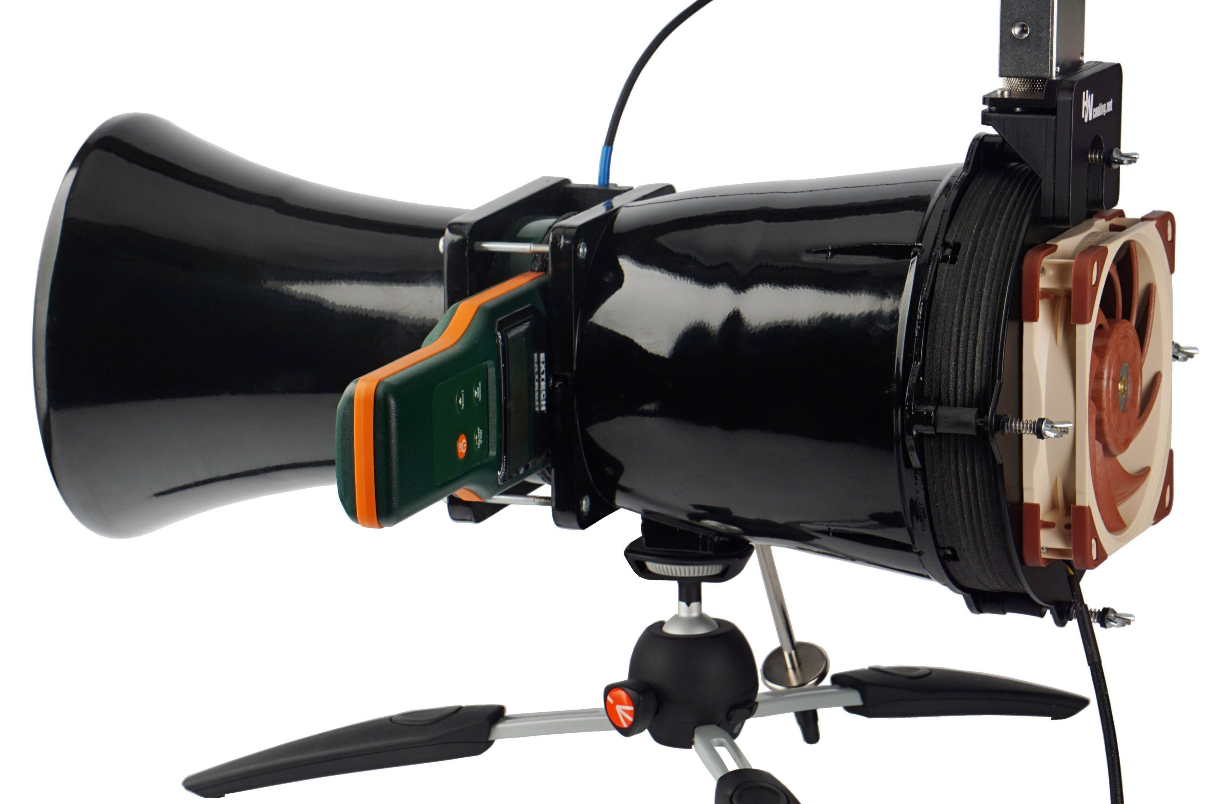
The individual parameters of the HWC wind tunnel for fan tests are the result of physical simulations and practical debugging. All the details (folds, material or finish used) have a rationale behind them and are designed this way for a specific reason. We will discuss the individual design details in turn in the description of the sub-variable measurements.
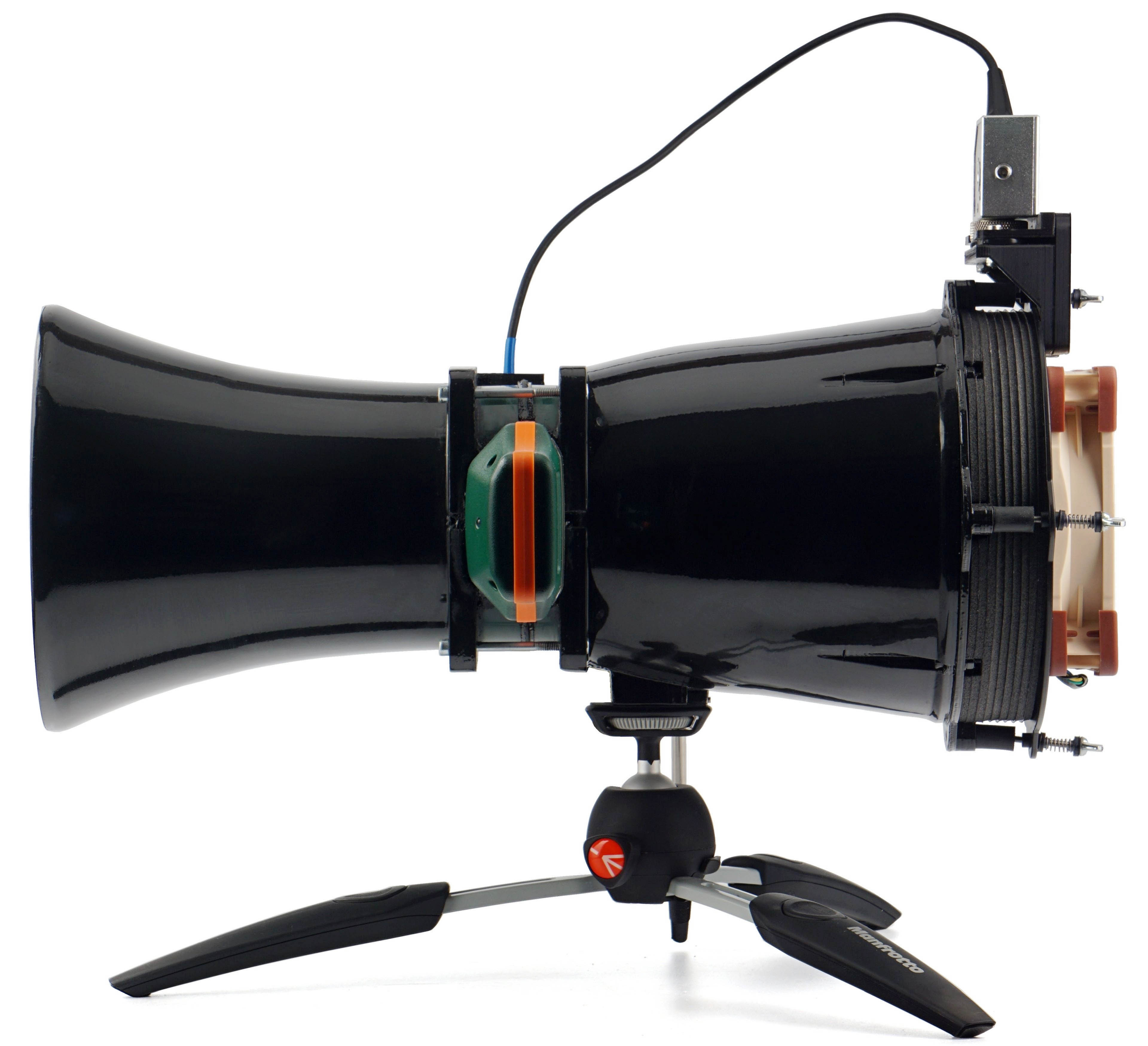
Now we will briefly elaborate on some things that do not fit thematically into the text of the following chapters. Namely, for example, that the skeleton of the wind tunnel is the work of a 3D printer (PLA). The rough print was, of course, then thoroughly machined by grinding, fusing, polishing and varnishing. Especially important is the smooth finish of the interior walls.
When joining the individual parts, the emphasis was on making sure that they fit together flawlessly, that they were sealed flawlessly (we will come back to this when we describe the test procedures for pressure measurement), but also that the joints were not loosened by use. Everything is disassemblable for servicing purposes, but it is ensured that the properties are maintained during use and, for example, even under the stress of vibration. The threads are secured with either lock nuts or thread-locking fluid. It depends on which is more suitable in which place.
When the wind tunnel is not in use, it is enclosed in a dust-tight chamber. In addition to the technical equipment and its correct storage, it is also important for objective outputs that all measuring instruments are calibrated according to the standard. Without this, it would be impossible to stand behind your results and rely on the manufacturers’ specifications. Calibration protocols are therefore an important part of the methodology. Testing is carried out at an ambient air temperature of 21–21.3 °C, humidity is approximately 45 % (± 2 %).
Fans come to us for testing in at least two pieces of the same model. If the deviations of any of the measured values are greater than 5 %, we also work with a third or fourth sample and the average value is formed by the results of the fans that came out the most similar and the differences between them fit under 5 %.



Hmm, the 100th fan in the database—counting 140 mm models as well. On Thursday, we’ll do a kind of recap or summary, where all fans tested so far will appear together in the charts. 🙂
After reading the methodology section I’m still uncertain about when the tests were performed with the obstacles infront or behind the fan. Could you please clarify that?
Scenario by scenario, it varies. The radiators (both thinner and thicker ones) are behind the fans, as they are more commonly used in practice, while the dust filters (both nylon and plastic) are in front of them, i.e. in front of the impeller. That also makes more sense.
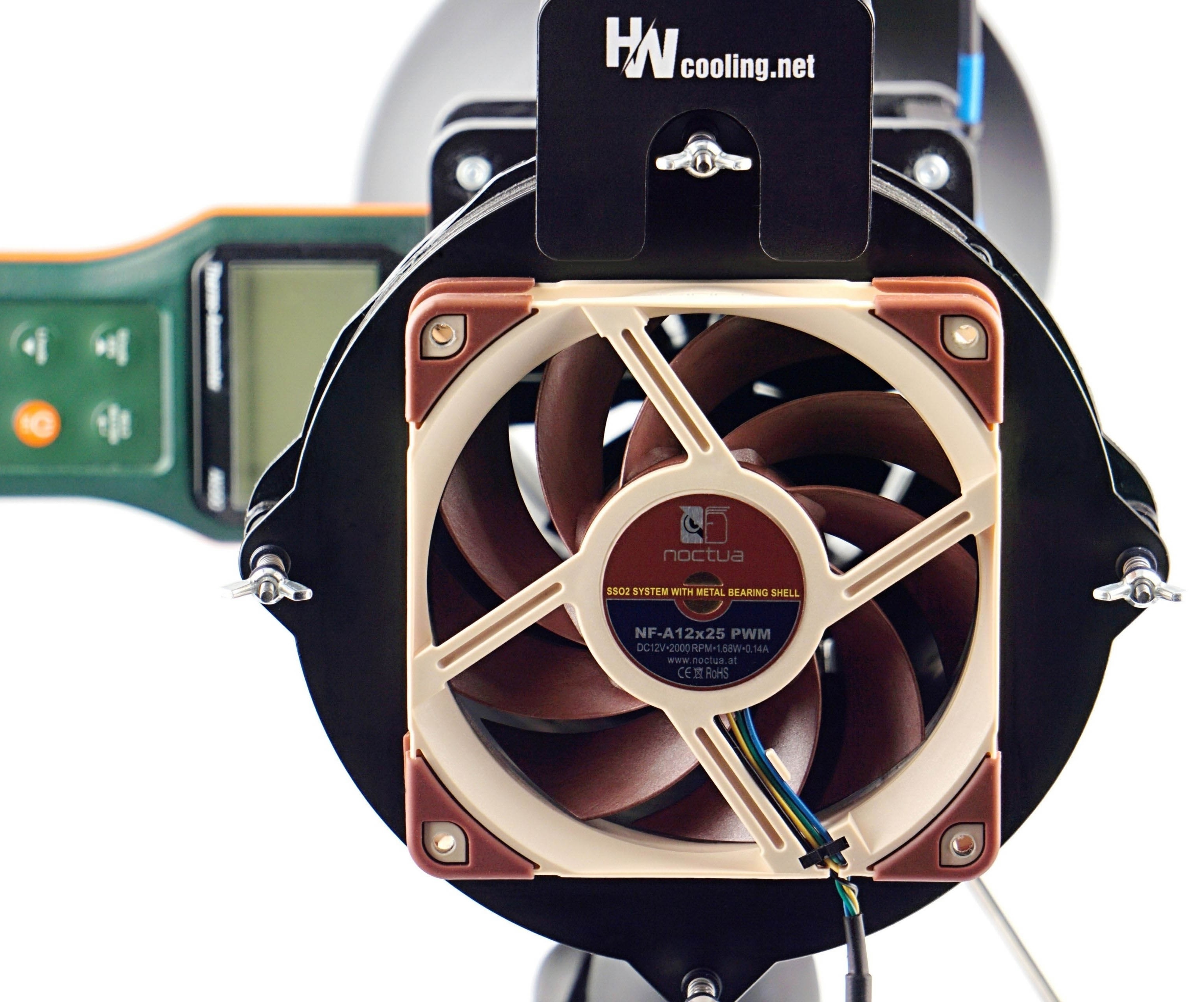
There is also a hexagonal grille in front of the fan, on the intake side, although in PC cases (for example, on the exhaust) it is often located behind it. We chose this placement because having it behind the impeller doesn’t change the acoustic profile very much, whereas with the opposite orientation, the difference can sometimes be quite significant, especially when it comes to tonal peaks. 🙂
Thanks for the clarification!
Your setup is what I was hoping for, for the reasons you already stated yourself. And just to make sure I’m not misunderstanding a fine detail: Whether **reverse blade fan or regular fan**, your dust filter test setup (both nylon an plastic) will always reflect typical real world usage, i.e. air will be “pulled” through the filter instead of being “pushed” through it. Right? Thanks in advance!
Yes, the dust filters are always on the intake side of the fans. 🙂
For the most accurate comparison possible, reverse fans are also positioned in the same relationship to the anemometer (in pull). That’s a more complicated discussion, but this is always the case regardless of the fan. If we did it the opposite way, in push, the area where we measure the wind/air speed—which is subsequently used to calculate the airflow in cubic units—would be too turbulent, and the results would therefore be distorted. 🙂