


The impeller is oriented so that, in the installed position, nothing visually obstructs the view. This refers to the stator struts, which can otherwise “spoil” the appearance. But this is not just about looks—it is about combining them with the efficient geometry of the proven five-blade design with a stabilizing ring (familiar from the P12 A-RGB). It is not exactly the same design, though, if only because what used to be behind the impeller is now in front of it.
Measurement of static pressure…
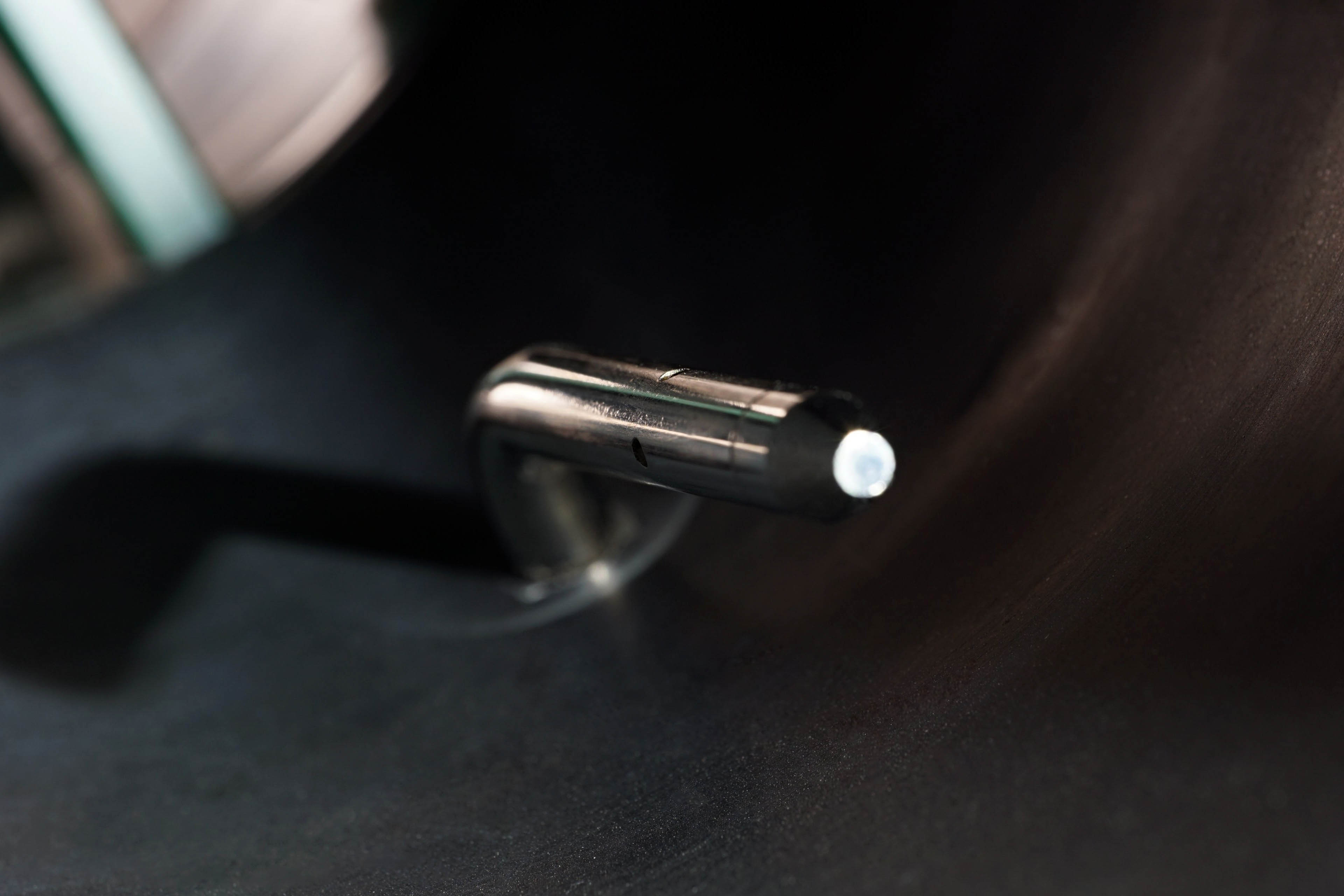
Finally, it is time to move further down the tunnel a bit. Just behind the fan is a static pressure sensing probe. Its position has been chosen with maximum measurement efficiency in mind. In other words, the sensors are placed at the points of highest pressure (although this is virtually the same everywhere in the unconstrained part of the tunnel).
The Fieldpiece ASP2, which is connected to the Fieldpiece SDMN5 manometer, is used to measure the static pressure in the tunnel. The latter also allows measurements in millimetres of water column, but we measure in millibars. This is a more finely resolved base unit for this meter. And only from there we convert the measured values into mm H2O to allow easy comparison with what the manufacturers state.
While we wrote when measuring noise levels that our results could not be compared with the parameters, that is no longer the case here. As long as the fan manufacturers do not embellish the parameters, they should quote approximately the same pressure values as our tests show. The most significant deviations can only arise at the level of varying accuracy of the measuring instruments, but these are negligible percentages.
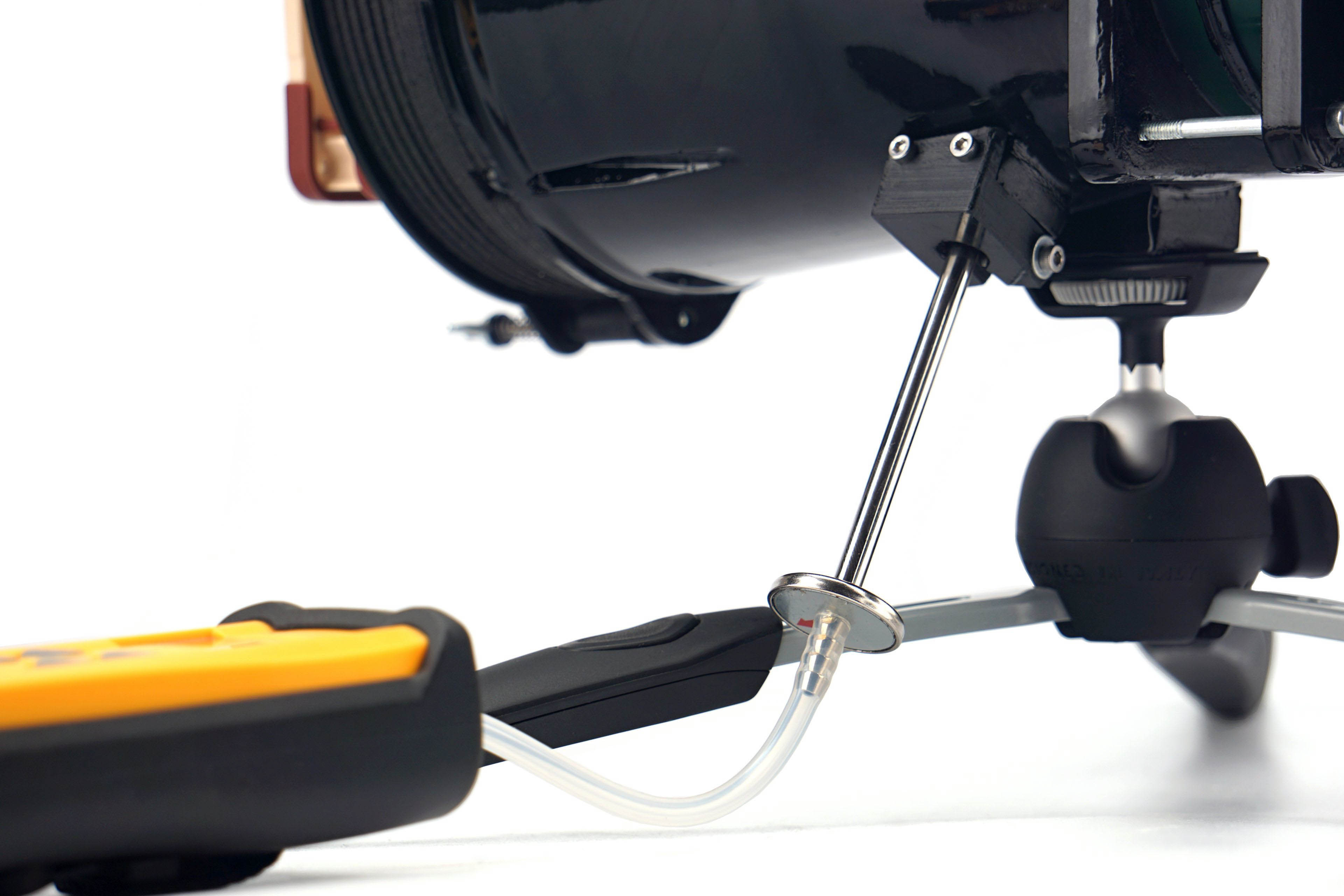
The greater the difference between the manufacturer’s claimed values and ours, the less the specifications correspond to reality. If the claimed values are significantly higher, it is certainly an intention to artificially give an advantage to the fans on the market. However, if the manufacturer quotes a lower pressure value than we do, it points to something else. Namely, a weaker tightness of the measuring environment. The less tight the tunnel is, the lower the pressure you naturally measure. This is one of the things we tuned for an extremely long time, but in the end we ironed out all the weak spots. Whether it’s the passage for the probe itself, the flanges around the anemometer, even the anemometer frame itself, which is made up of two parts, needed to be sealed in the middle. Finally, the flap at the tunnel outlet must also be perfectly tight. That’s because static pressure has to be measured in zero airflow.
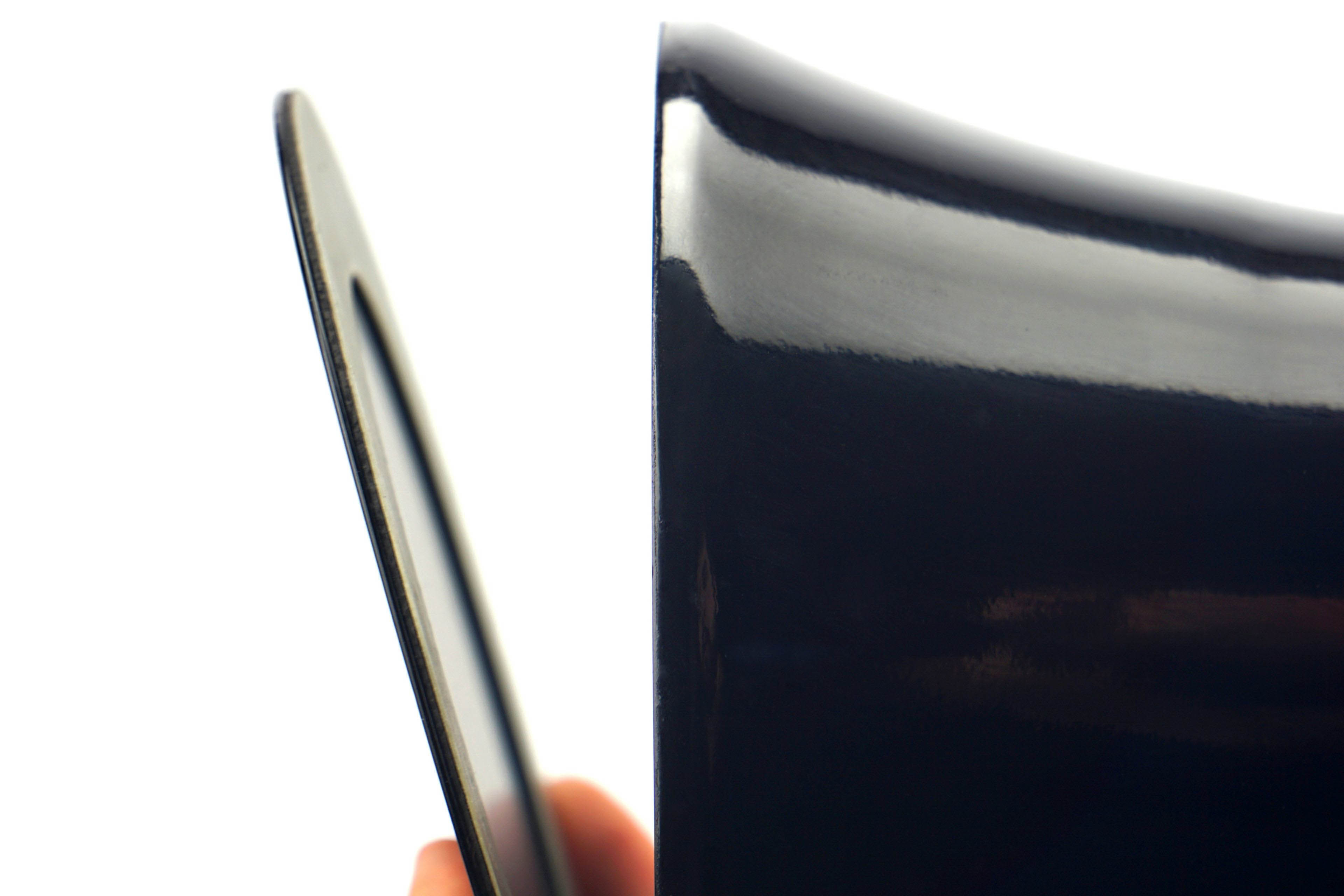
But there is one thing that often lowers the pressure of the fans a bit. And that’s protruding anti-vibration pads in the corners or otherwise protruding corners. In other words, when the fan doesn’t fit perfectly to the mounting frame at the inlet, and there are small gaps around the perimeter, that also affects what you measure. But we have not gone into this because it is already a quality feature of the fan. In the same way, it will “stand out” and perform a bit weaker than it has the potential to do with better workmanship, even after application by the end user.



Hmm, the 100th fan in the database—counting 140 mm models as well. On Thursday, we’ll do a kind of recap or summary, where all fans tested so far will appear together in the charts. 🙂
After reading the methodology section I’m still uncertain about when the tests were performed with the obstacles infront or behind the fan. Could you please clarify that?
Scenario by scenario, it varies. The radiators (both thinner and thicker ones) are behind the fans, as they are more commonly used in practice, while the dust filters (both nylon and plastic) are in front of them, i.e. in front of the impeller. That also makes more sense.
There is also a hexagonal grille in front of the fan, on the intake side, although in PC cases (for example, on the exhaust) it is often located behind it. We chose this placement because having it behind the impeller doesn’t change the acoustic profile very much, whereas with the opposite orientation, the difference can sometimes be quite significant, especially when it comes to tonal peaks. 🙂
Thanks for the clarification!
Your setup is what I was hoping for, for the reasons you already stated yourself. And just to make sure I’m not misunderstanding a fine detail: Whether **reverse blade fan or regular fan**, your dust filter test setup (both nylon an plastic) will always reflect typical real world usage, i.e. air will be “pulled” through the filter instead of being “pushed” through it. Right? Thanks in advance!
Yes, the dust filters are always on the intake side of the fans. 🙂
For the most accurate comparison possible, reverse fans are also positioned in the same relationship to the anemometer (in pull). That’s a more complicated discussion, but this is always the case regardless of the fan. If we did it the opposite way, in push, the area where we measure the wind/air speed—which is subsequently used to calculate the airflow in cubic units—would be too turbulent, and the results would therefore be distorted. 🙂