


Some really attractive things are often overlooked or given less attention than they deserve, for various reasons. This is somewhat the case with the technically remarkable fan from PCCooler CPS – the F5 R120. This 120 mm fan with its features is in the company of the most prominent names, although it has its weaknesses as well. These may or may not interest you either. It depends on the use case.
… and of airflow
With airflow measurements, we can well explain why the test tunnel is shaped the way it is. It doesn’t consist of two parts just so that the “exhaust” can be conveniently clogged for pressure measurements. The anemometer (i.e. the wind speed measuring instrument) is held together by two parts, two formations, through the flanges.
The front part, at the beginning of which the fan is mounted, becomes steadily narrower and from about two thirds of the way through the cross-section is smaller than that of a 120 mm fan. The reason for this is that the cross-section of the anemometer is always smaller than that of the fans tested. The taper towards the anemometer fan is as smooth as could be chosen and the tunnel walls are smooth. This has minimized the occurrence of unnatural turbulence.
The difference between the cross section at the intake (fan under test) and at the constriction point (anemometer) also means a difference in dynamic pressure, the principles of the Venturi effect apply here. In order to avoid distortion at this level and to ensure that the fan airflow is not different from what it actually is, the Bernoulli equation must be applied to the measured values (for maximum accuracy, the calculation also takes into account the internal cross-sectional area of the anemometer, i.e. its inactive part ). After all this, it is again possible to confront our results with the paper parameters.
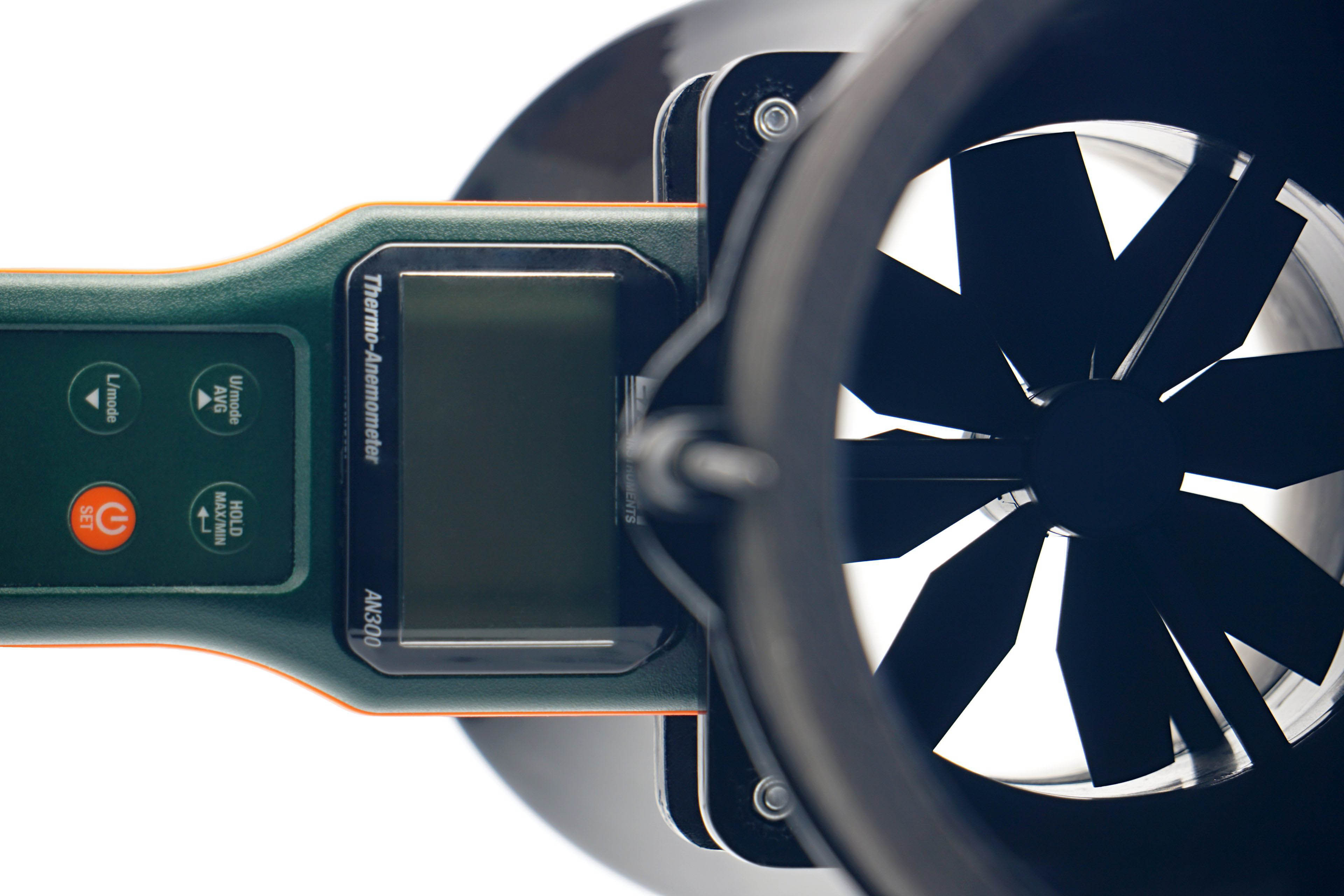
We use an Extech AN300 anemometer with a large 100 mm fan for the measurements. Its big advantage over other anemometers is that it is made for bidirectional sensing. This allows tests at different fan orientations. However, the “pull” position is more suitable or accurate for measurements, even though it may not seem so at first glance, but we’ll explain.
Here, we get to the second part of the tunnel, the part behind the anemometer. It is part of the whole device, mainly to allow a laminar flow of air to arrive at the impeller of the anemometer. Otherwise, uncontrolled side whirls would be reflected in the results, which are inconsistent with accurate measurements. Therefore, we will test the flow in the pull position. If anyone would like us to elaborate more on this topic, we can elaborate further at any time in the discussion below the article. Ask away. 🙂
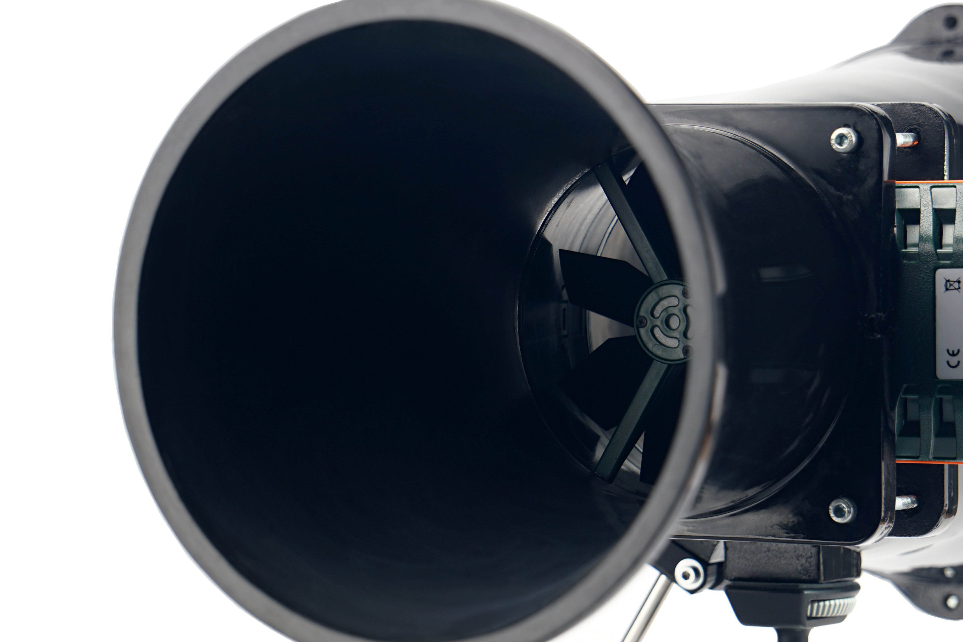
In regard to the anemometer, we shall return for a bit to noise measurements and to setting modes according to fixed noise levels. It may have occurred to you as you were reading that the anemometer fan is also a source of sound that needs to be filtered out when measuring fans. For this reason, we insert a securing pad between the frame and the anemometer fan before each measurement and mode setting according to the fixed noise level. This, by the way, also holds the anemometer fan during static pressure measurements.




That’s a very a good fan overall. No noticeable weakness with decent noise profile, at a highly competitive price point. I’m surprised that a PBT only fan without an outer ring can perform this well. I wonder how the Arctic P12 Max compares (maybe it’s comparable to the ARGB version?)
P.S. Frequency plots aren’t accessible in the English version, and most (all?) links in the conclusion page are broken due to lacking -bk.
Thanks! Fixed. 🙂
The motor sound link is still broken. It’s the first plot in the “hexagonal grille” page, right?
So, this sound only appears when speed is very close to the minimum RPM? I don’t think I’ve seen this behaviour before, interesting. It should be easily avoidable by the user, but can be limiting for those who want an extremely quiet build.
Haha, no mistake escapes you. What a great thing that we have such attentive readers. 🙂
And yes, it’s the first spectrogram with the hexagonal grille. This mode has the lowest fan speed at which frequency analysis of sound is measured. Several fans with typically cheaper motors are struggling at the lower speed limit and this behaviour is accompanied by such annoying sounds. I don’t always point it out, but here it was extra interesting especially in the context of high efficiency at very low speeds. When you go from that optimum 700 rpm down to somewhere near 550 rpm, it may not be so great anymore. Because of that annoying motor sound that adds to the well audible spectrum.
The blades of the F5 R120 are relatively short yet thick. Although we did measure some vibration, I don’t think it was due to the blades being “too flexible”. Something else will be behind their occurrence, maybe some manufacturing inaccuracies (around the axle for example) and such. The lower MTBF value would suggest this, but I don’t want to speculate on these things.
What is obvious, however, is that even a cheap fan with shorter PBT blades doesn’t have to be the source of any vibration. We have already been convinced of this by a test of 15 Stratus 1220 PWMs, where the variance of vibration across the samples is very wide. But it is given by the high tolerances. If the vibrations were due to blade undulations, we would never, on any piece, measure 0.000. And in that one case (the gold sample) this happened even at maximum speed with a fairly high (1600) RPM.
Strongly recommand you to add the 9RA1212P4G001, and maybe the 9RA1212P1K001 and 9RA1412P1G001 from Sanyo into the compaing list.
Thank you for the useful tips. We will definitely take a look at the fans and try to add them to the results database. I can’t promise when this might happen, but we will contact Sanyo and see.